
Welcome to the next installment of Project LS-Z. Last I left you a few weeks ago, we got the entire Sikky swap kit installed into the 350Z. It really was pretty simple since they did all the fabrication, engineering, etc. Now we dig into the work that isn’t as straight forward. Here we go…
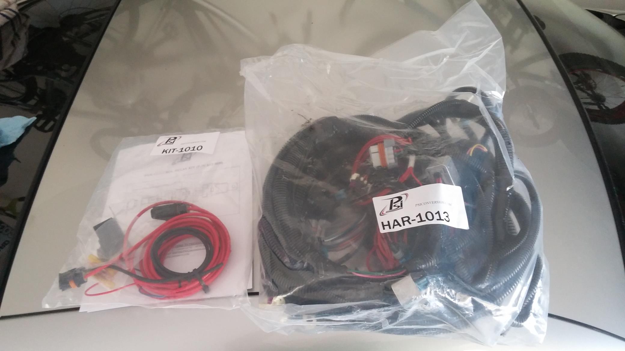
First up, the wiring harness. I decided to go with PSI Conversions LS1 wiring harness. There are many options to go with when it comes to wiring. You can use your old stock LS1 wiring harness and send it off to one of many people that will modify it for your application, or you can choose a company that will build an entire brand new harness with new wires, new connectors, etc. I went the new route from PSI. Thanks to PSI for fielding multiple phone calls from me, as this was the part of the project I was most worried about. They assured me it wasn’t going to be that bad.
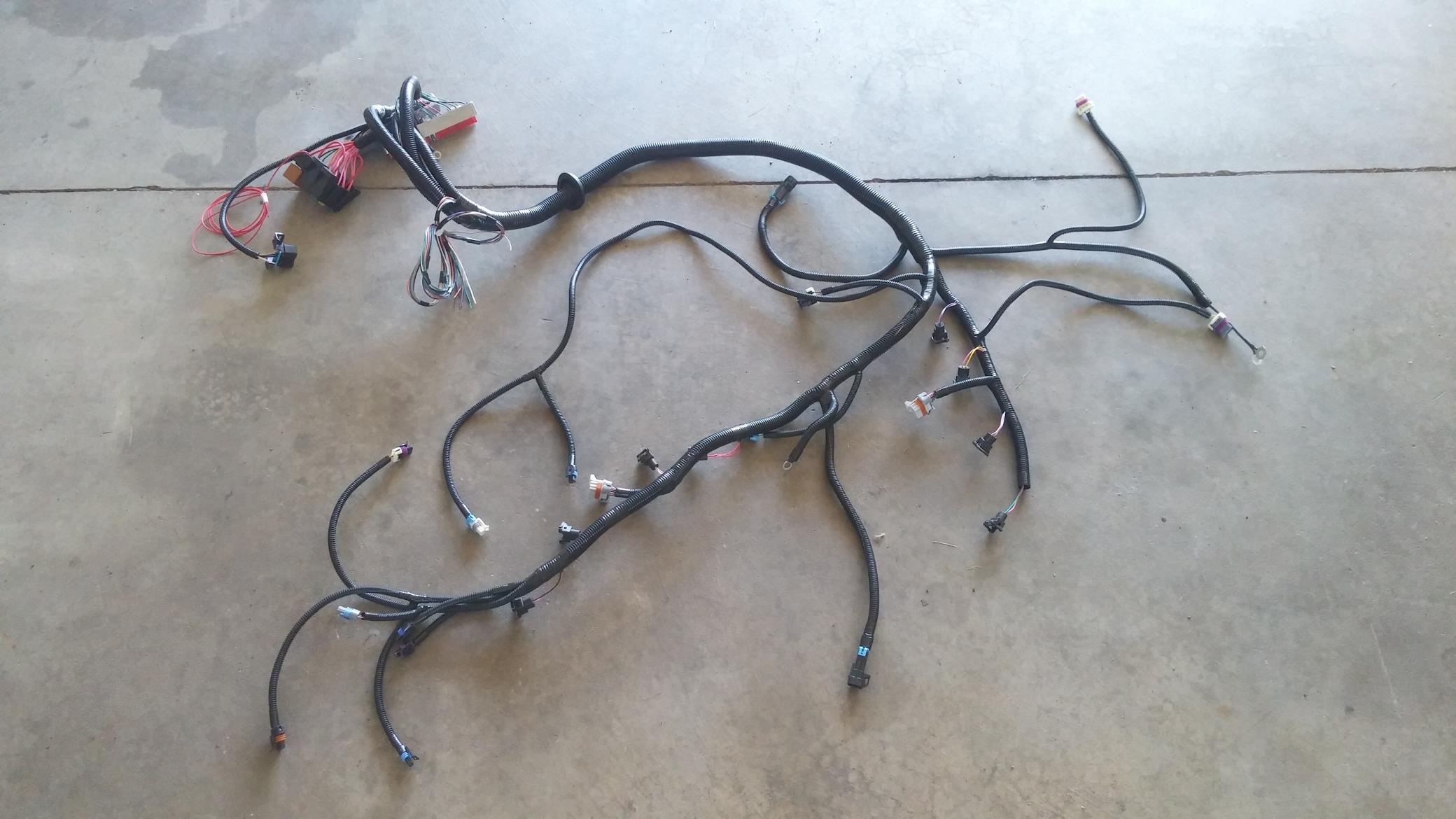
I wont bore you with the details of all the wiring but it really wasn’t that bad, just like they told me. The harness was perfect. The wire lengths, connectors, etc were spot on. It did not take long at all to just plug everything in. I routed the ECU plug-ins through the same location the stock Z harness ran. The plan at this point was to mount the LS ECU to the modified stock Z ECU bracket on the passenger side behind the dash.
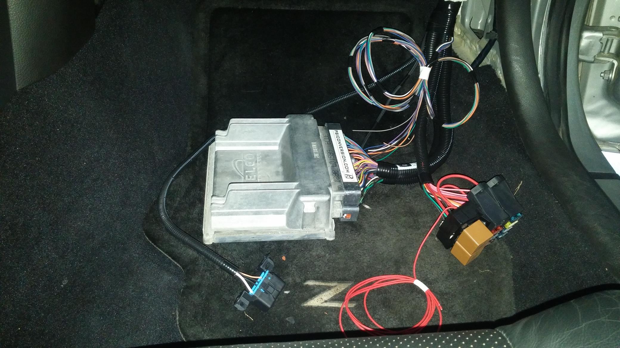
While waiting for the wiring harness, I had the LS ECU sent out to remove the VATS (security system), emissions codes disabled, speed limiter raised, fan on/off temps adjusted, and other settings to fit the swap. Only $65 from a guy on eBay, and it was back in just a couple days.
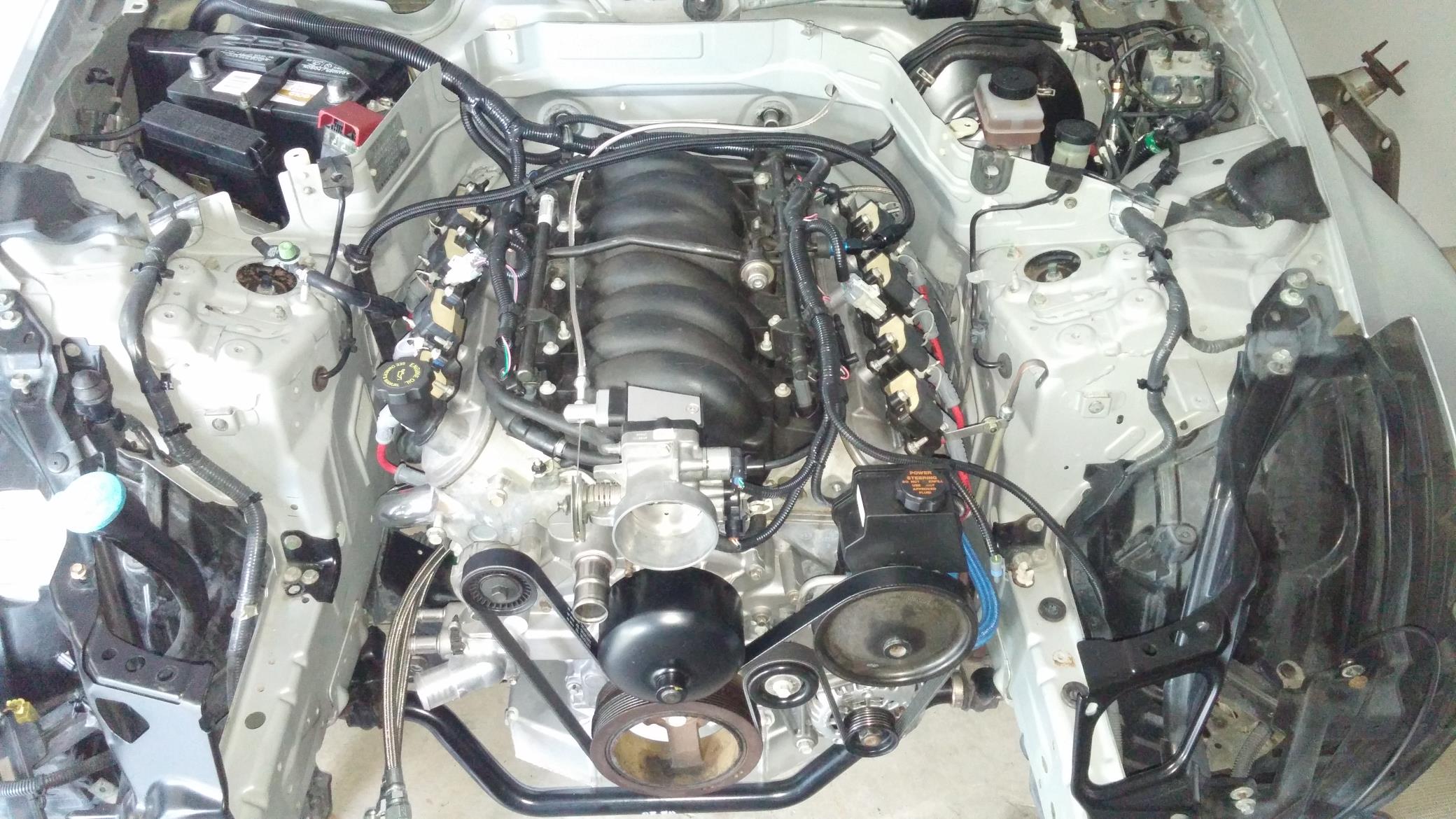
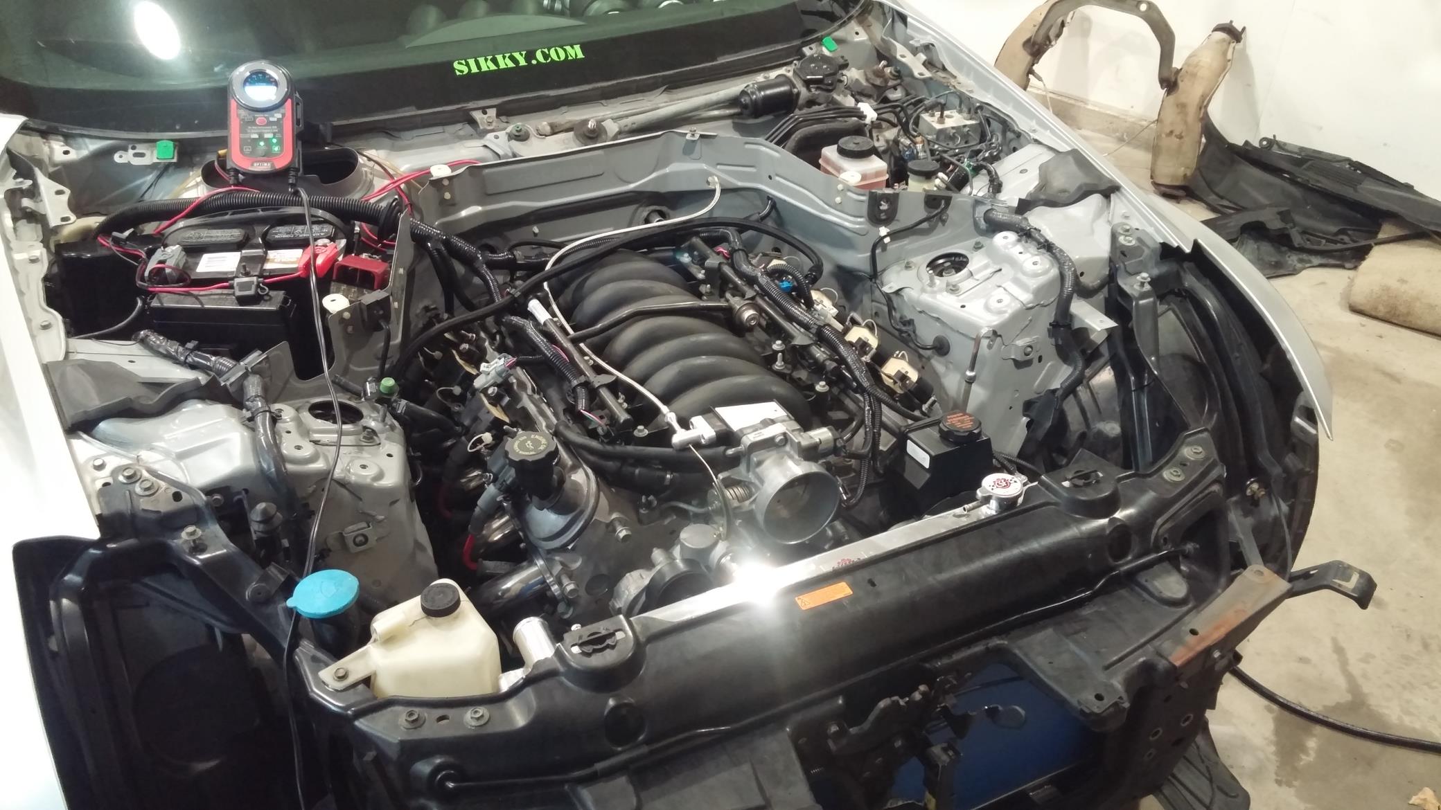
What time is it? Time to start it! We have fuel. We have the electrical hooked up. Lets see what happens.
Glorious noises! Still a lot to put together. Time to press on.
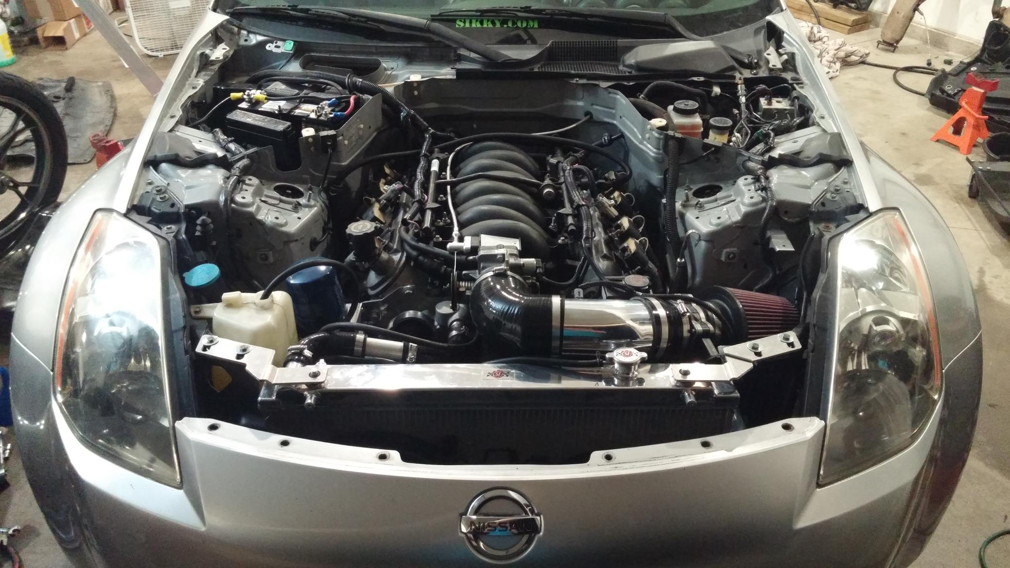
A stock 350Z radiator would be sufficient for a stock LS1 in your normal driving situations. The intention of this car is to spend a lot of time attacking time, so the stock radiator will not cut it. Enter Anish and Speed Freaks USA. Thanks to their generous sponsorship of GridLife events, and Team 365Racing.net success, we were able to win product credits towards CSF cooling products. They sent us a dual-core 350Z replacement radiator meant to fit right in the stock 350Z radiator support. Fitment was great, as it slid right in place. This thing has some huge cooling capabilities compared to stock. It was probably three times the thickness. It’s starting to look like a car again!
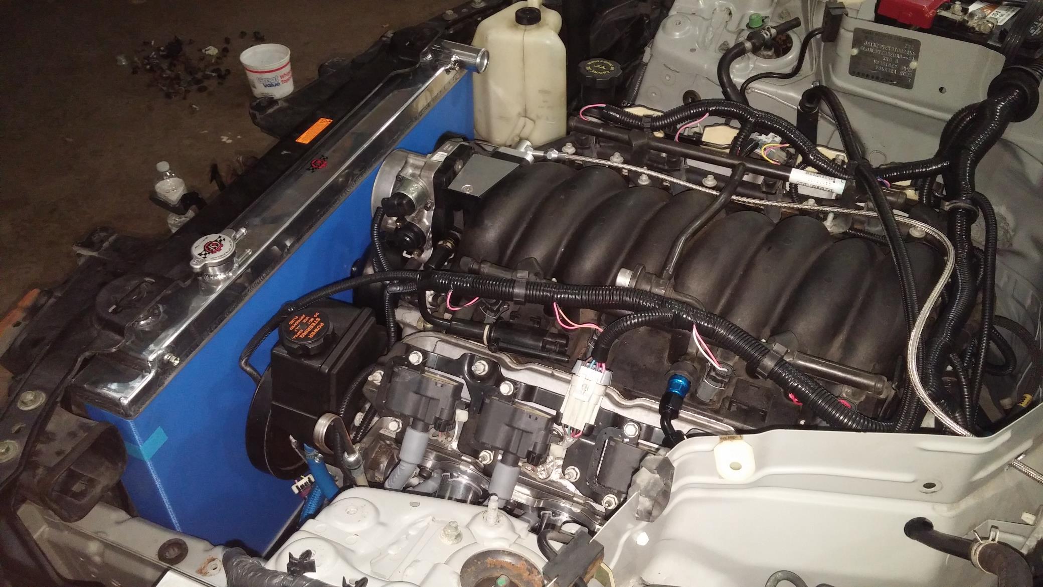
Now this is where the fun begins. We’ve all seen this point in some build, not just an LS swap Z. This is the detour, the road block, the fork in the road (whatever you want to call it) This moment should be of no surprise to anyone reading this; building a car, working on a car, rarely, if ever, goes 100% as it should. Well here is that point in my build. The point where I’ve seen multiple LS swap people put up their car for sale and give up because of some snag. Above I mentioned how much larger the new radiator is. When Sikky built the kit with the stock radiator in mind, there are no issues with intake clearance to the radiator, motor mount location, etc.
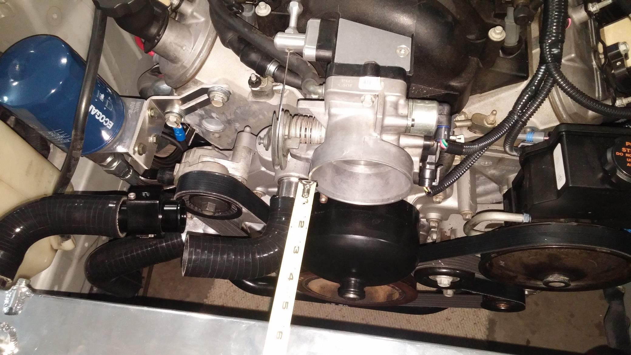
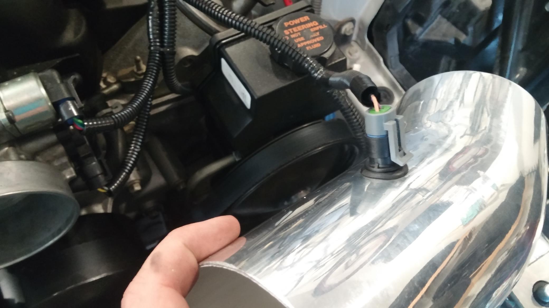
In the picture below, the stock radiator tucks into the black support at the bottom of the picture. Lots of room for that to fit if using stock stuff. Stock throttle body diameter = 4 inches. And this is where I’m at…
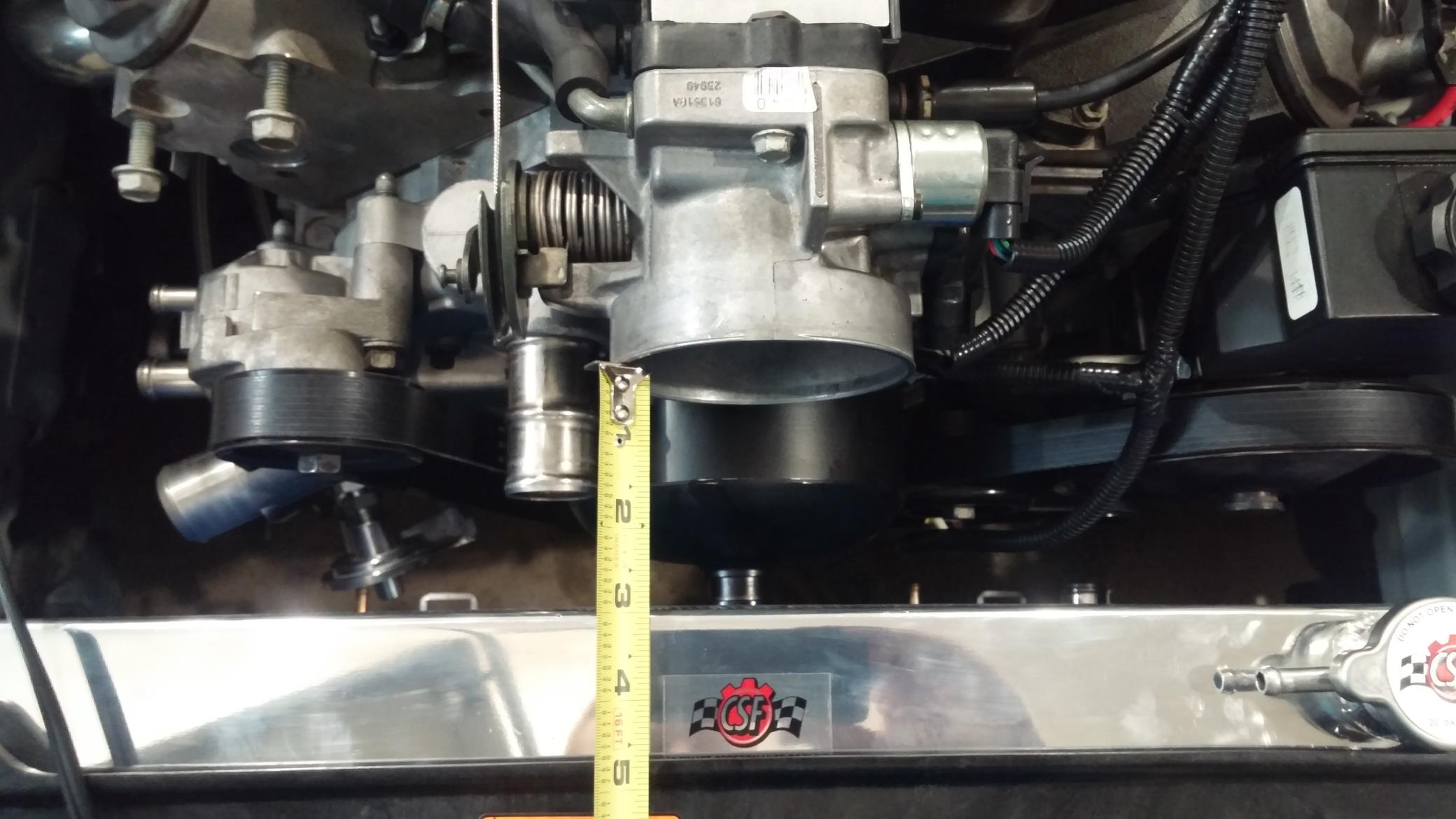
Well this isn’t good. A 4 inch intake elbow isn’t going to fit into a 3 inch space. Sikky has a newly developed, really nice intake for LS swaps. There was no way in heck that was fitting on my car at this point. Dejected, I boxed the intake back up and sent it back. At this point I wasn’t sure what I was going to do. One idea I tried was a Corvette intake bridge.
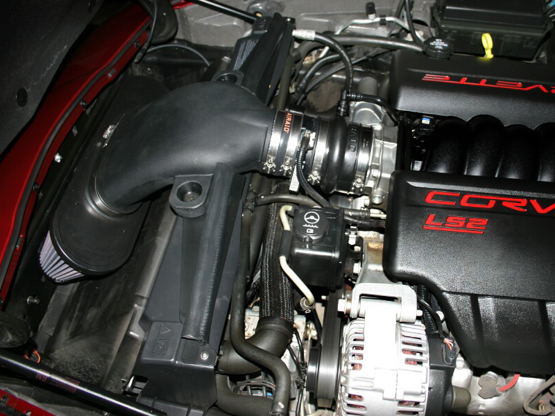
This was no where close to fitting either. Time to brainstorm and come up with a solution.
In the meantime, I needed to get the oil filter mounted to something. I designed a bracket to mount to the cylinder head that will work for now. Eventually when I get an oil cooler requiring new oil lines, I’d like to make a new bracket to mount the filter where the AC compressor bolts to the bottom of the motor. The lines supplied with the Sikky kit are just too long to do that right now.
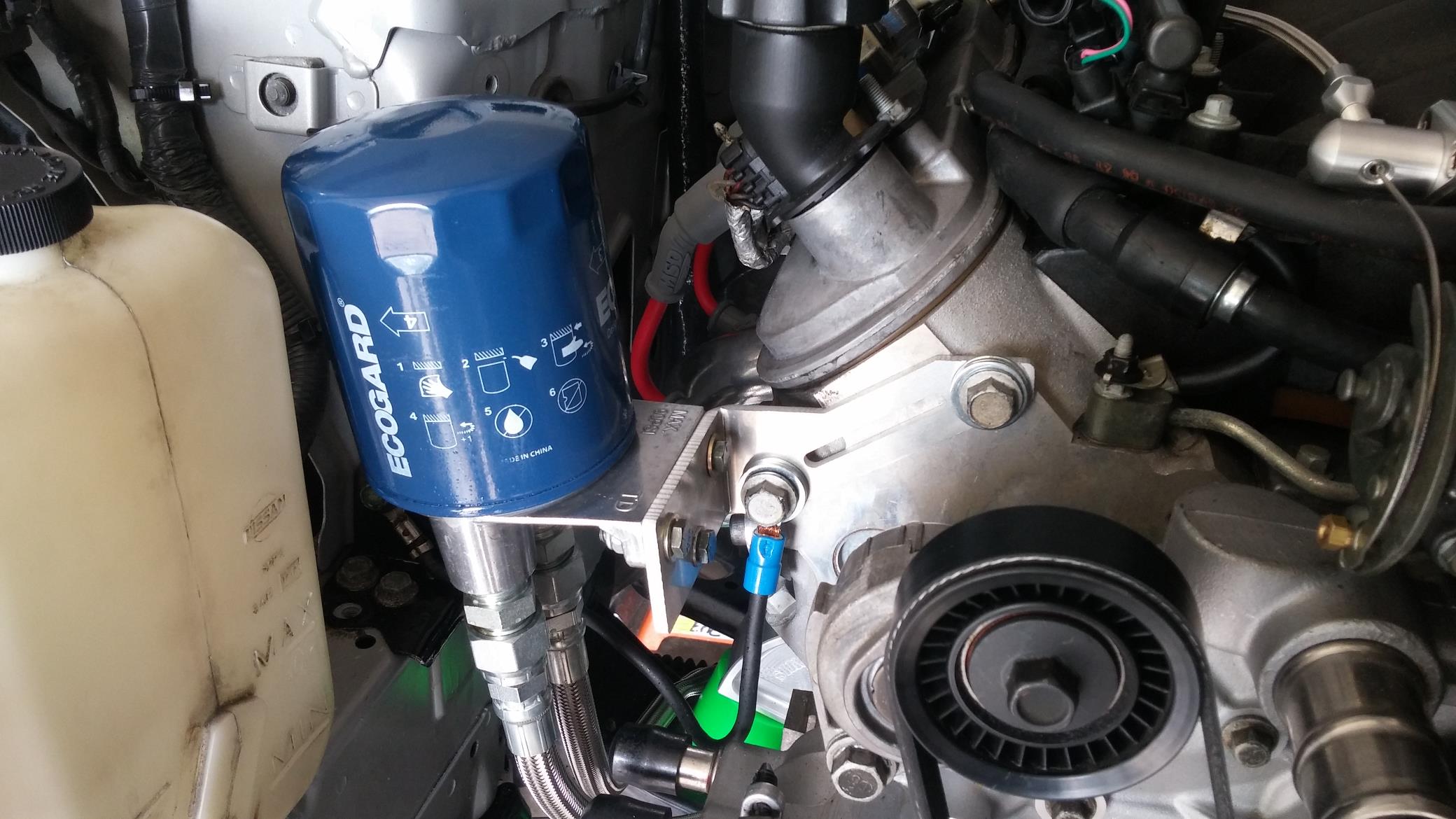
Yes, it makes a mess when you unscrew it. In my head I thought the filter being mounted up like that would drain the oil back down into the oil pan. Apparently oil filters have some sort of baffling in them that holds the oil in the filter. It makes sense so you don’t end up with dry starts more than likely. This will get changed eventually.
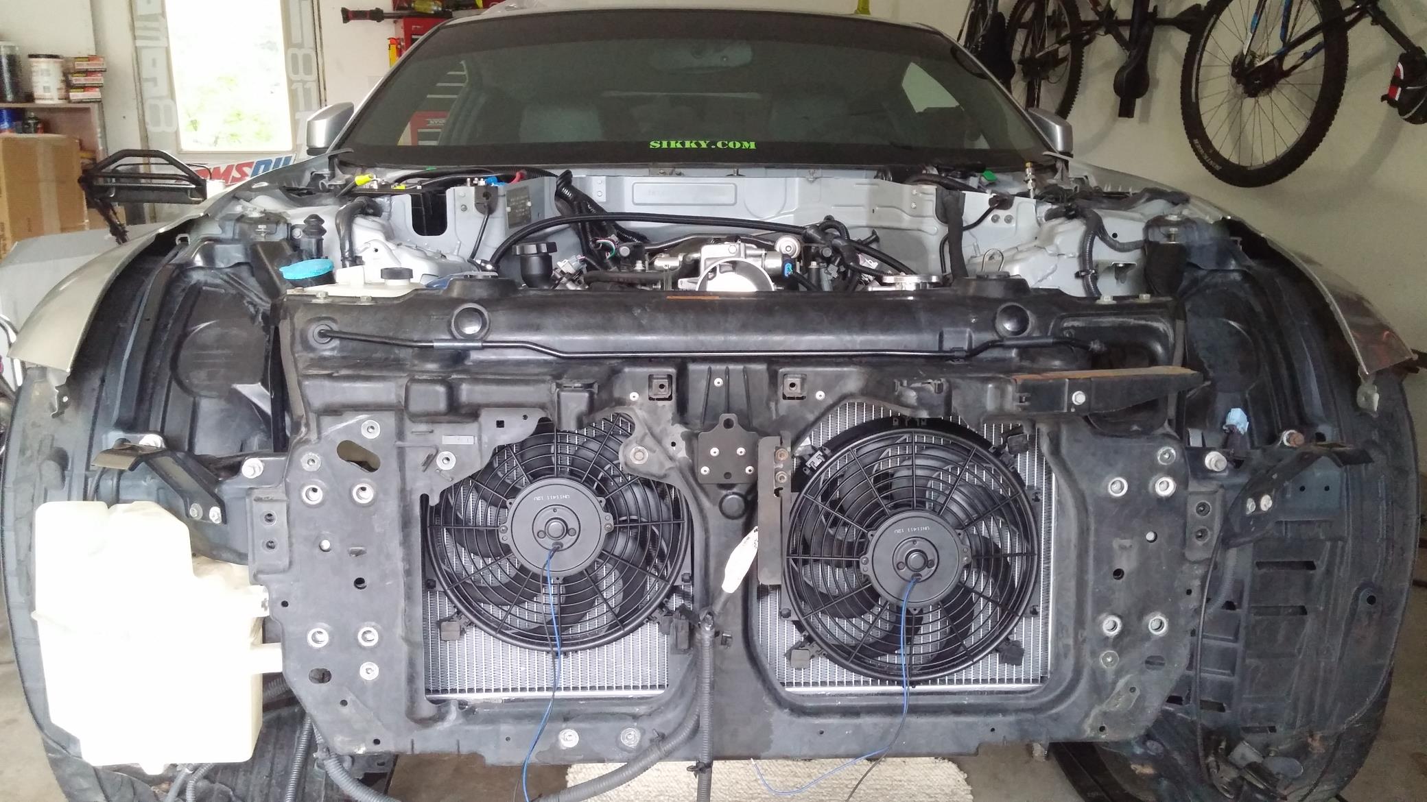
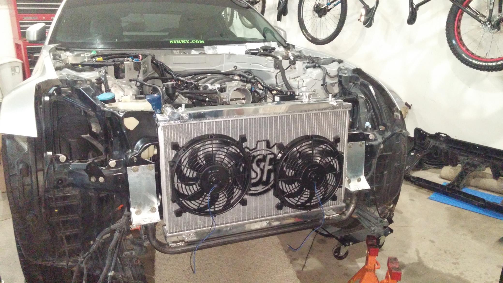
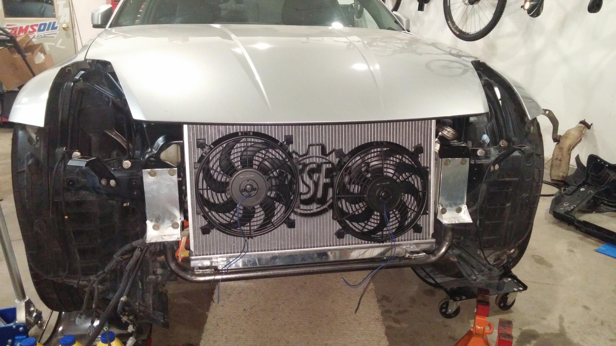
To continue on the cooling system, the radiator needed some fans. Measured up the openings in the stock radiator support and ordered some fans and got them mounted and wired up. The 12 inch fans fit nicely in the openings.
I needed to keep this project rolling, so I had to figure out what to do with the intake/radiator clearance issue. The dual core radiator was required. The stock radiator support is a plastic/fiberglass type material, so there really isn’t any modifying that could be done. This is when I decided I was just going to make my own radiator support. The reason this was a tough direction to go was because I lose the mounting points for just about everything on the front end such as air bag sensor, temp sensor, horn, washer fluid tank and a few other things. This also meant that I was going to lose my hood latch and hood pins would be required. Re-engineering the front of the car isn’t something I was looking forward to, but there weren’t any better options at my disposal.
Now the fans look tiny on the giant radiator without the stock shroud around them. Lets hope they offer enough air movement.
Hood test fit
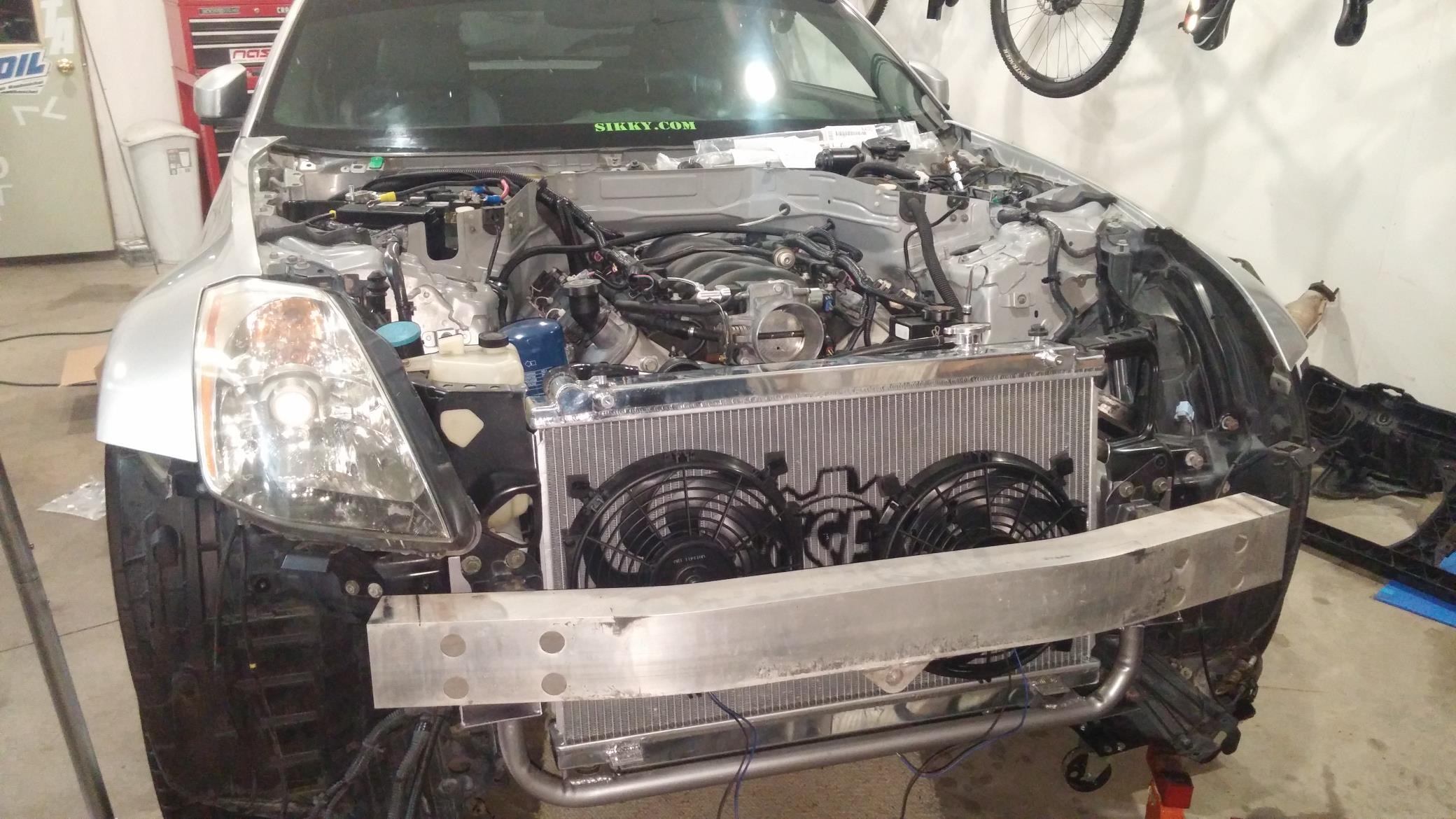
Crash beam installed
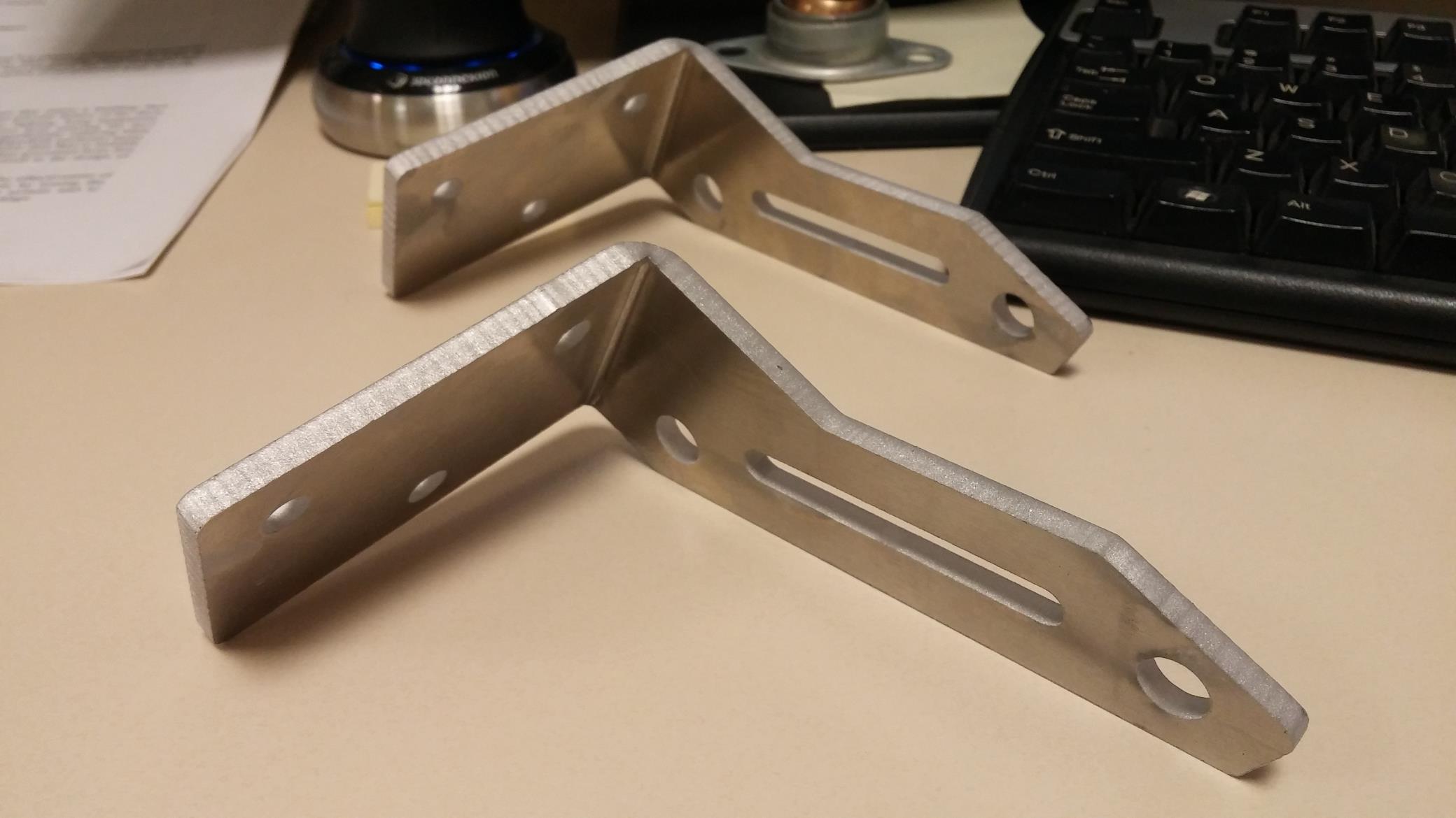
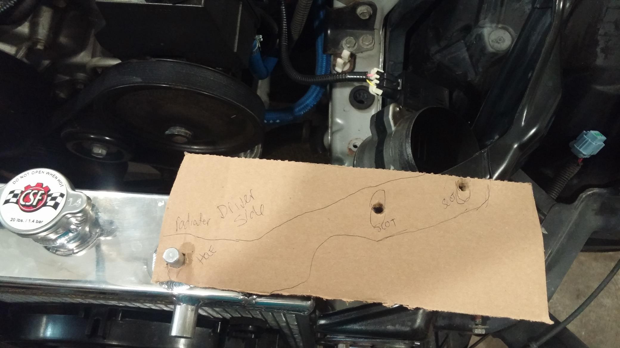
Next, I needed some upper radiator mounts, so I made a template, designed some brackets up on the computer, had them cut on the water jet, and then formed.
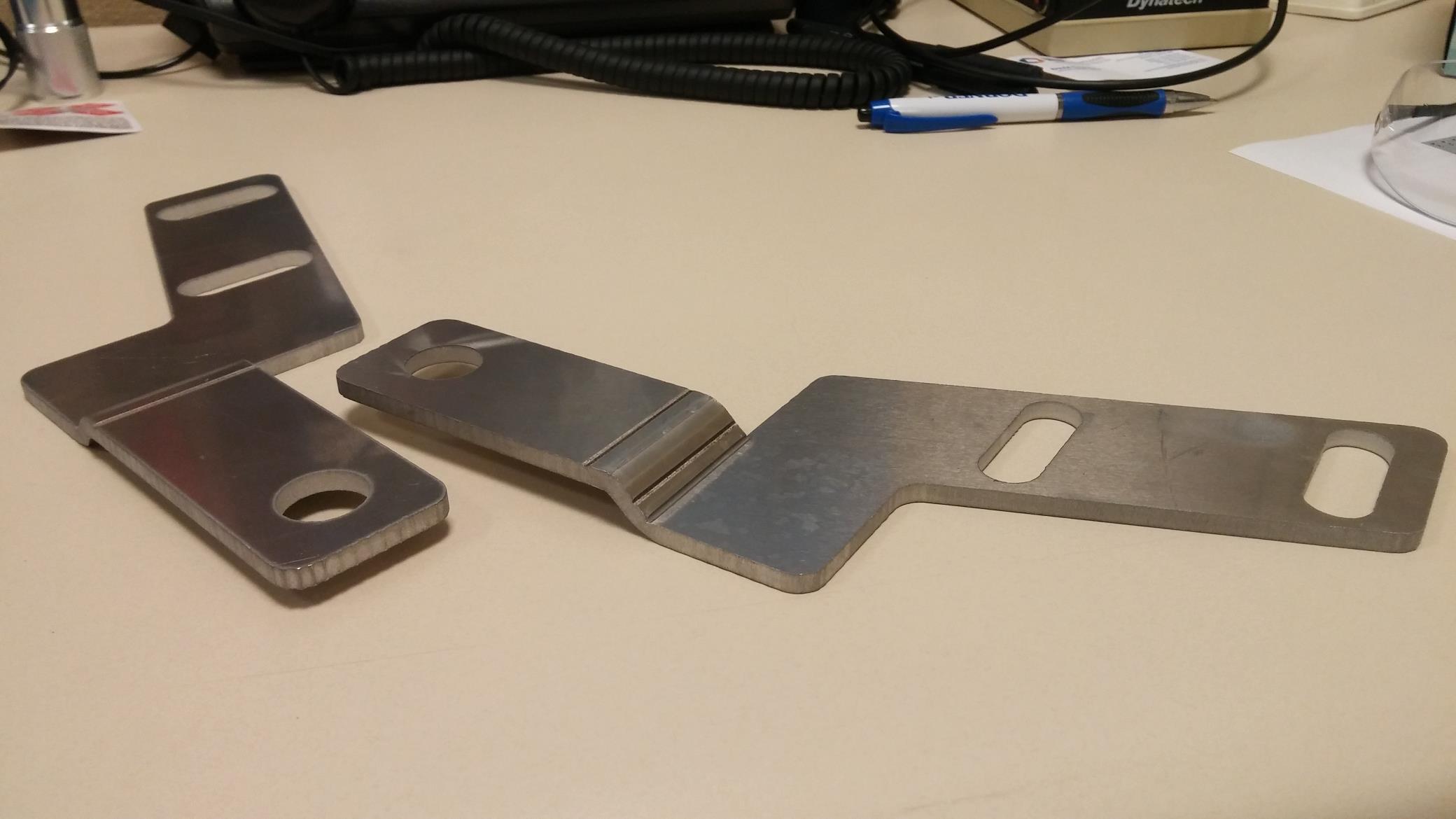
And the end result. Lots of room!
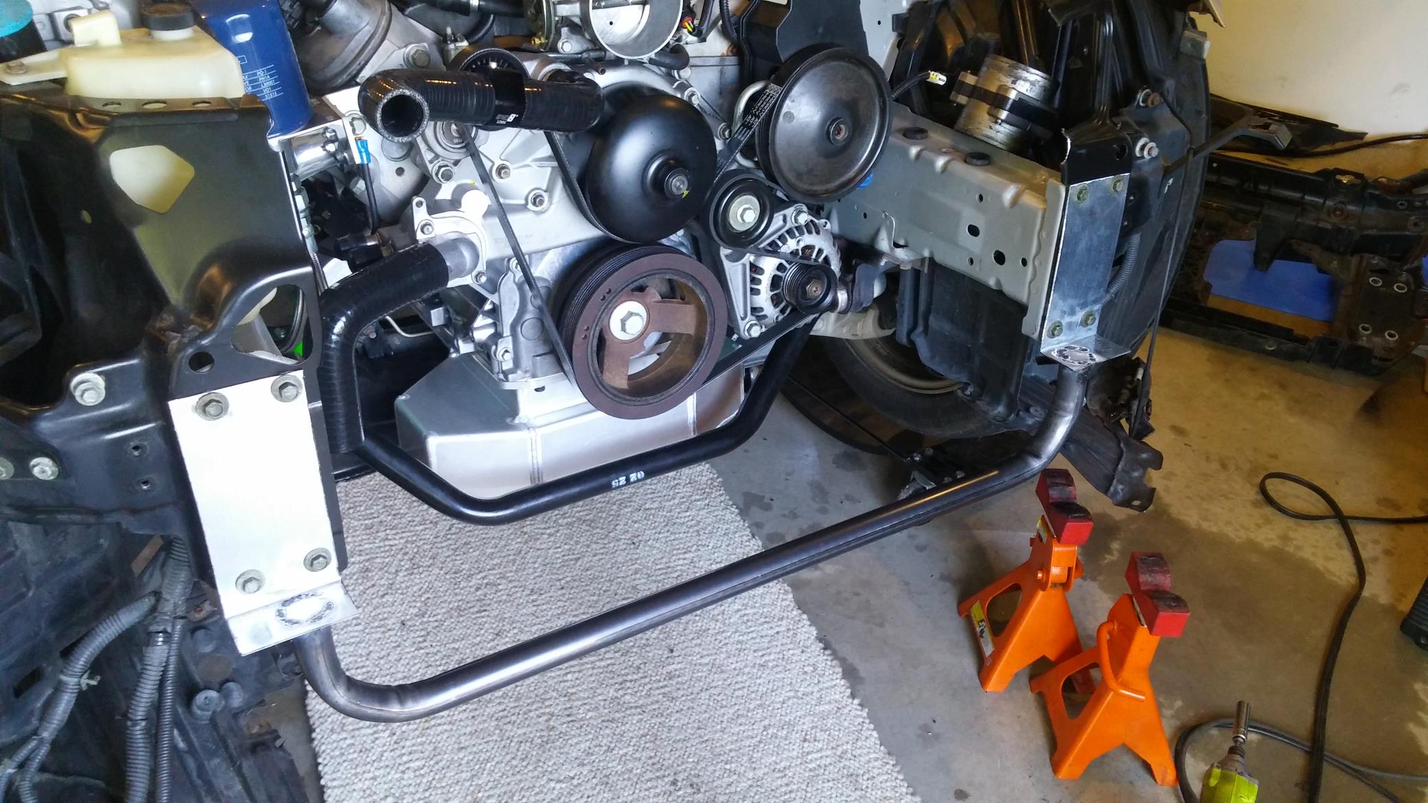
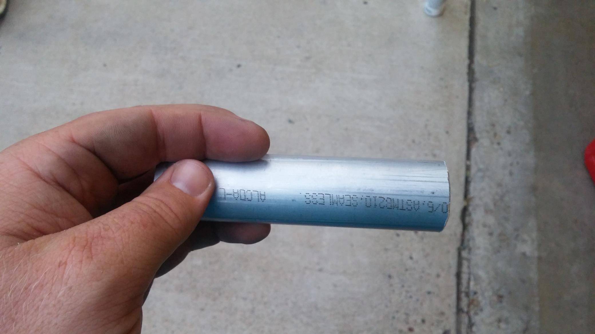
With that sorted out I could move onto connecting coolant lines and making an intake. Because there is no LS swap 350Z specific coolant hoses, I had to piece my own together. I ordered the required silicone 90º bends, reducers, and straight tube from Pegasus Auto Racing. Their selection was awesome and made it easy because none of the fittings are the same size. LS water pump fittings are 1-1/4″ and 1-1/2″, while the CSF radiator had 1-3/8″ fittings.
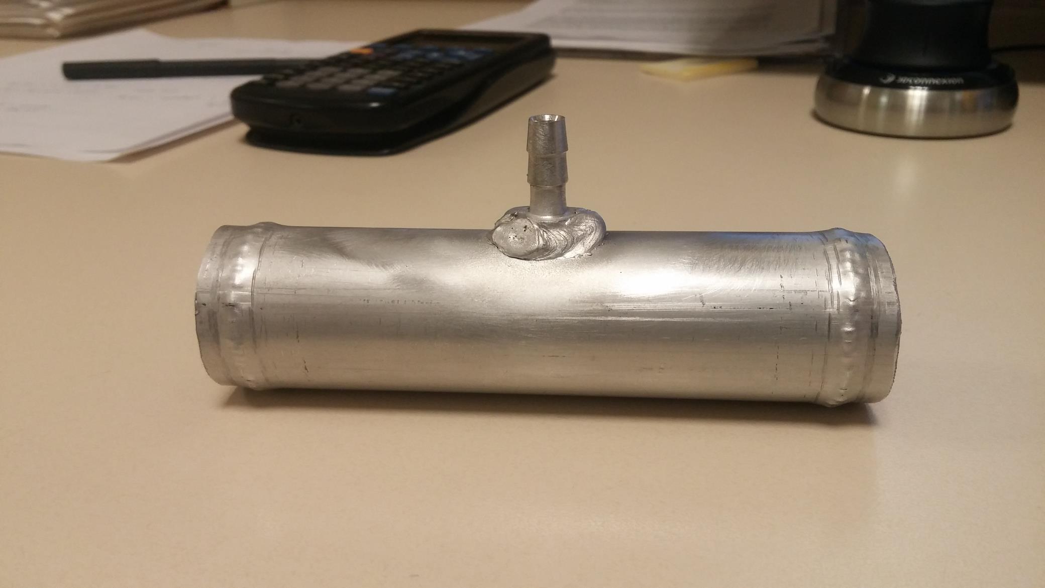
I found a cool trick on the internet. Aluminum coolant couplers/connectors are expensive, like $15/ea and I needed a lot of them. If you have a lineman crimping pliers and some aluminum tube laying around you can make your own connectors with a “bead roll” on the end.
Ta da, I just saved myself $75+
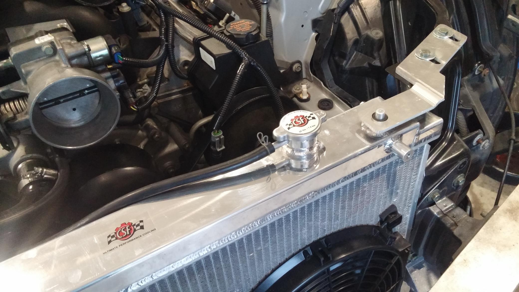
At first I had the coolant steam line from the heads run to the overflow tank. I later found out that line needed to be plumbed into the pressurized coolant system. An aluminum hose barb was added to the upper radiator hose for this purpose.
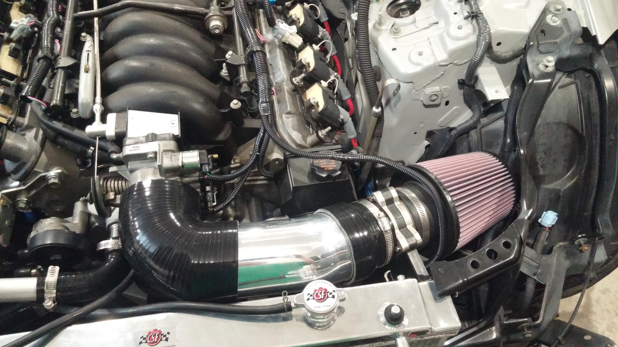
One last engine bay project for now to get this thing on the ground for a test drive. Time to make an intake. I could have just reordered the Sikky intake kit and had a nice finished bolt on kit to install, but I wanted to give making my own a try. A few couplers, an aluminum elbow, and a K&N filter and I was ready to go. The LS1 has a separate intake temperature sensor that I also had to make provisions for. A simple hole saw and a rubber grommet did the trick.
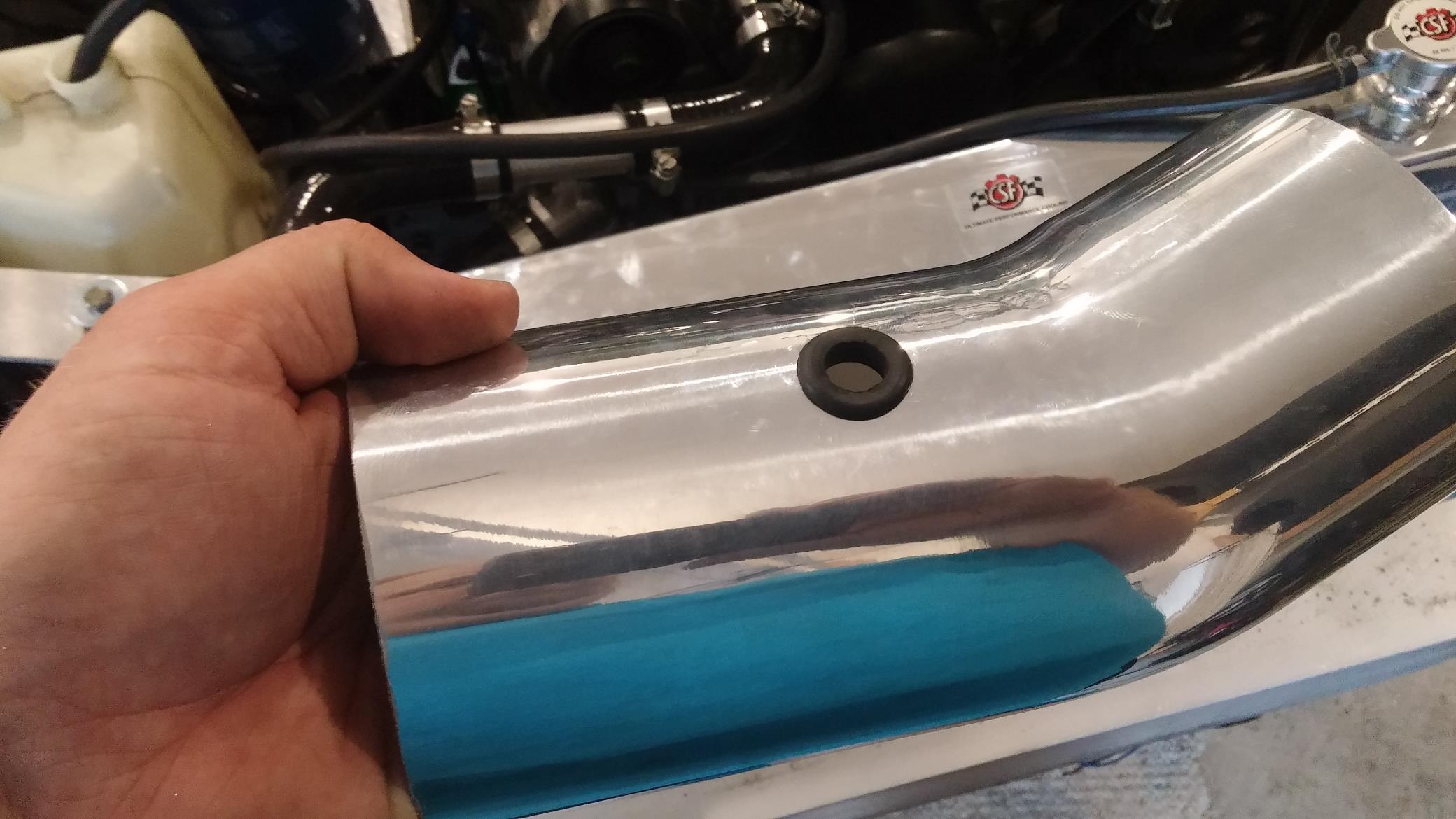
The finished product. I’m not much of a chrome guy, so I plan to have this powder coated black later on.
Throw the headlights back in, and bolt the bumper back on and you end up with this. I was feeling pretty proud of my car at this point 
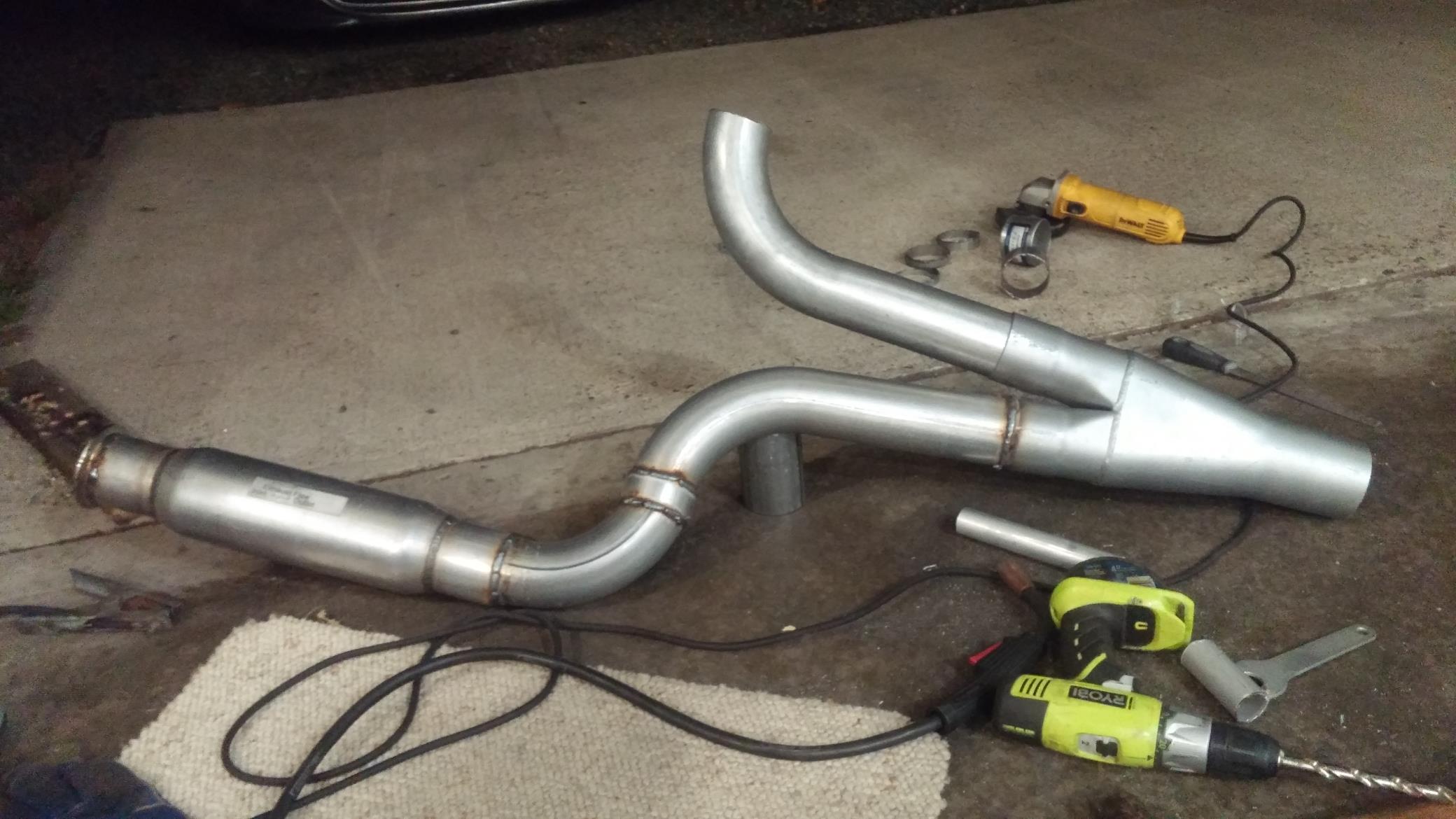
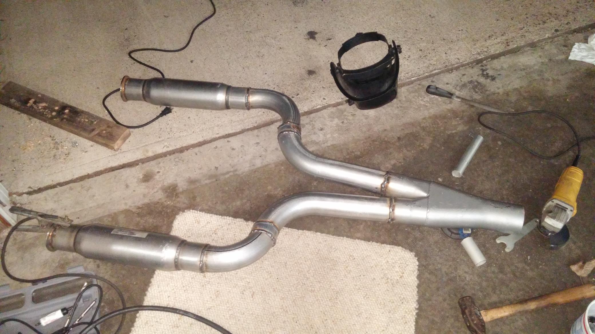
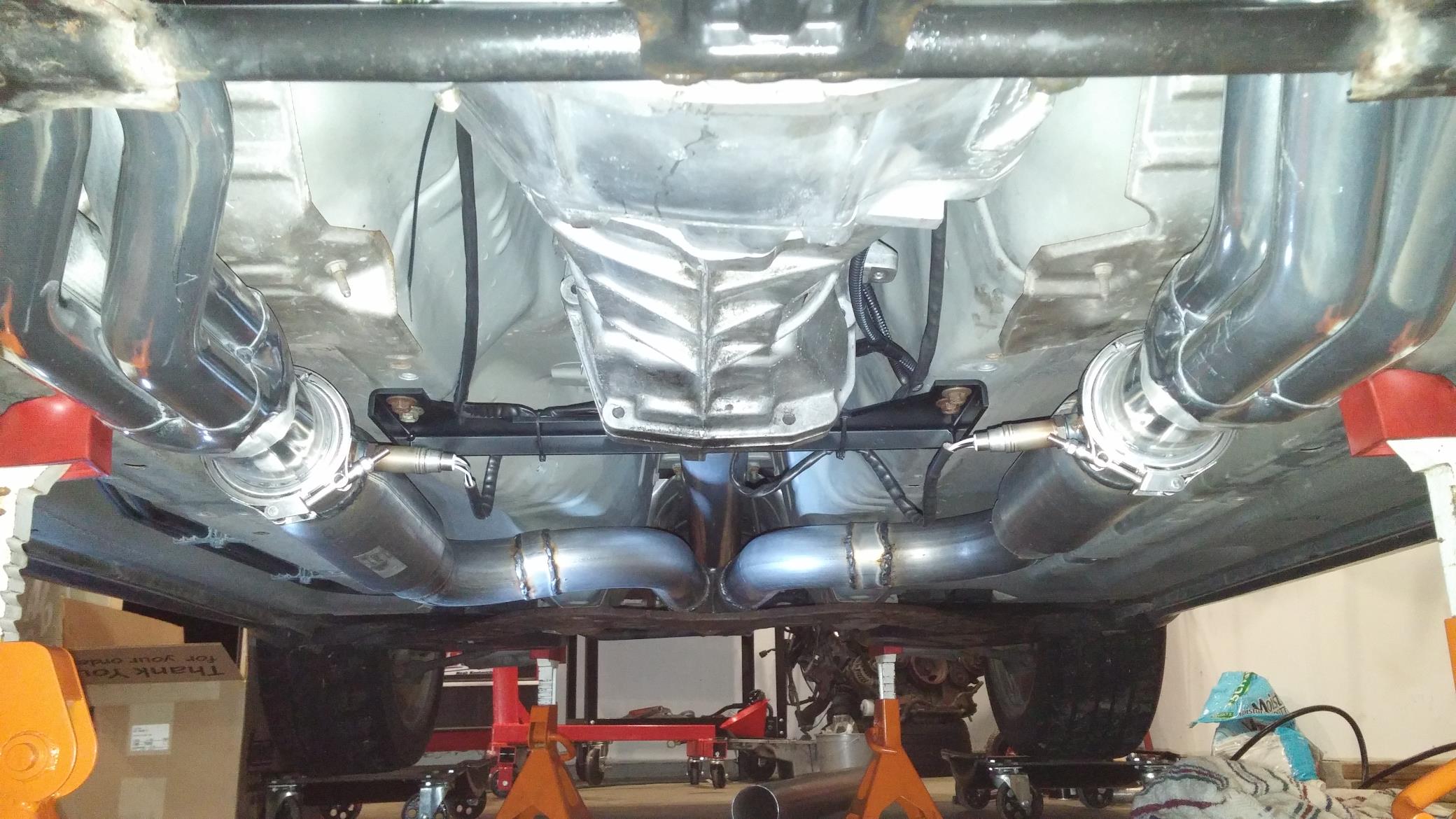
Now just an exhaust (or partial exhaust) and I can take this thing of the jackstands and go for its first drive! I said this on Facebook, but props to anyone that is good at building exhaust systems/headers/etc. The next few pictures took me somewhere around 5 hours of labor to complete. Welding v-band flanges to the mufflers. Cutting angle after angle on the bends to get the exhaust to meet up with the Flowmaster y-pipe just right. Tacking everything in place, double checking fitment. Drilling holes for O2 bungs for the O2 sensors. It was tedious, and it was time consuming, but I think it turned out well for a garage built exhaust y-pipe. The exhaust is 3″ off the headers through 12″ long, 3″ glasspack mufflers. It then meets at the Y-collector which transitions to a single 3.5″ exhaust from the rear diff to the back of the car.
This is a good place to end this update. I know I said the last update was long and lots of pictures, but this one will probably top it. If you’re keeping score, this gets us up to Road America Optima weekend on the timeline of events. The week to follow this was preparing the S2000 for SCCA Nationals in Lincoln, Nebraska and doing my best to get the LS-Z ready for a shakedown at MAP’s Proving Grounds 2015.2. We will pick up the next update of Project LS-Z preparing for its maiden voyage!
Until then, take care and thanks for following along!