Well here it is. One of the most sought after DIYs for the LS-Z swap. Credit for the idea goes to Mike Jordan. Words and pictures by me, Eric Koehler
**Disclaimer: Read through the whole thing first before you start doing this. This is not a perfect retrofit. As I will point out later on, the sweep angle between the stock gauge and this replacement gauge are not quite perfect which leads to the tach not reading 100% accurate. I consider this a “get me by” for the moment. With further research/testing the could work out alright should someone choose to take there.**
You are going to be using the “guts” of the donor gauge and retrofitting them to your stock cluster.
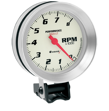
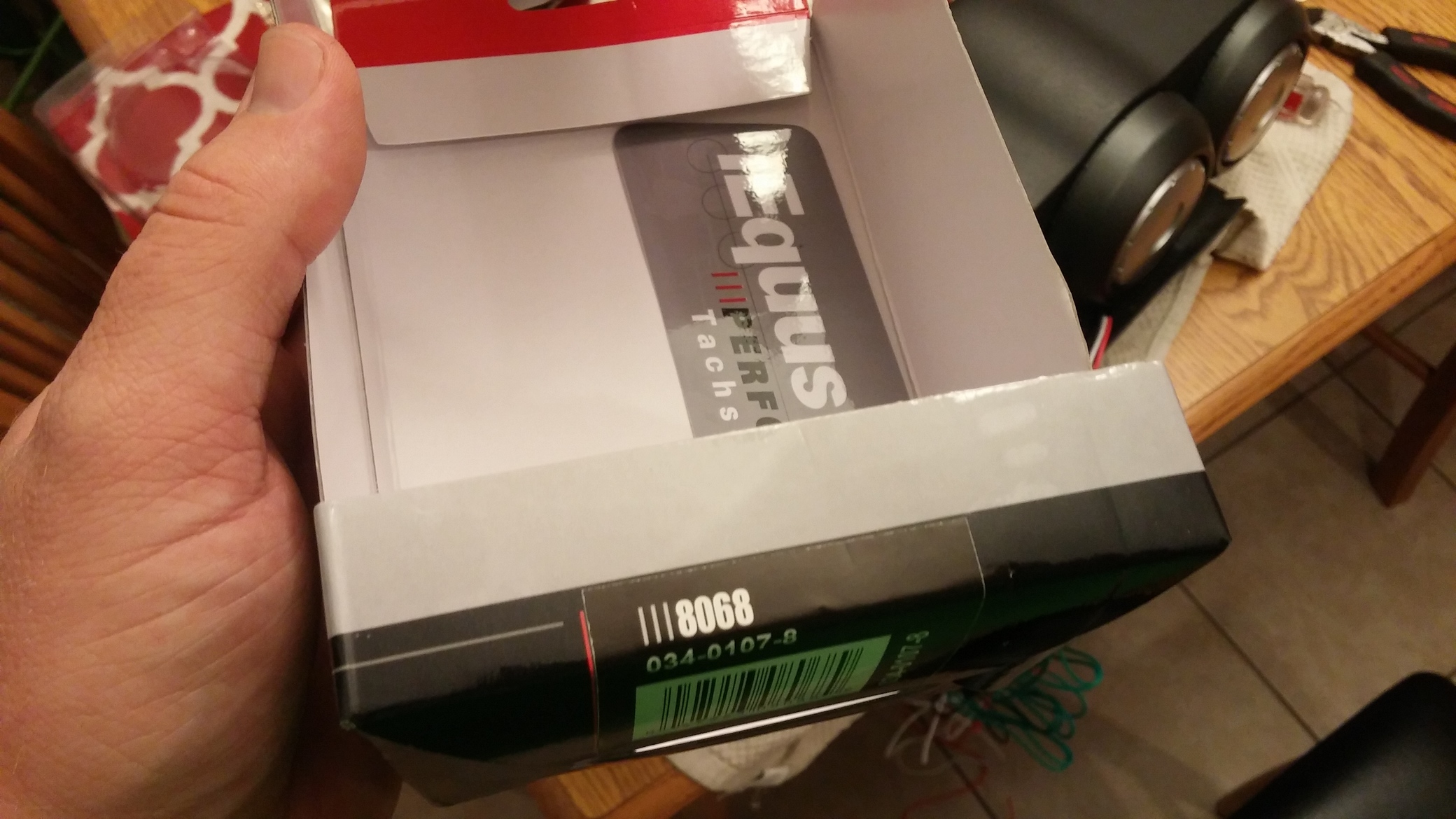
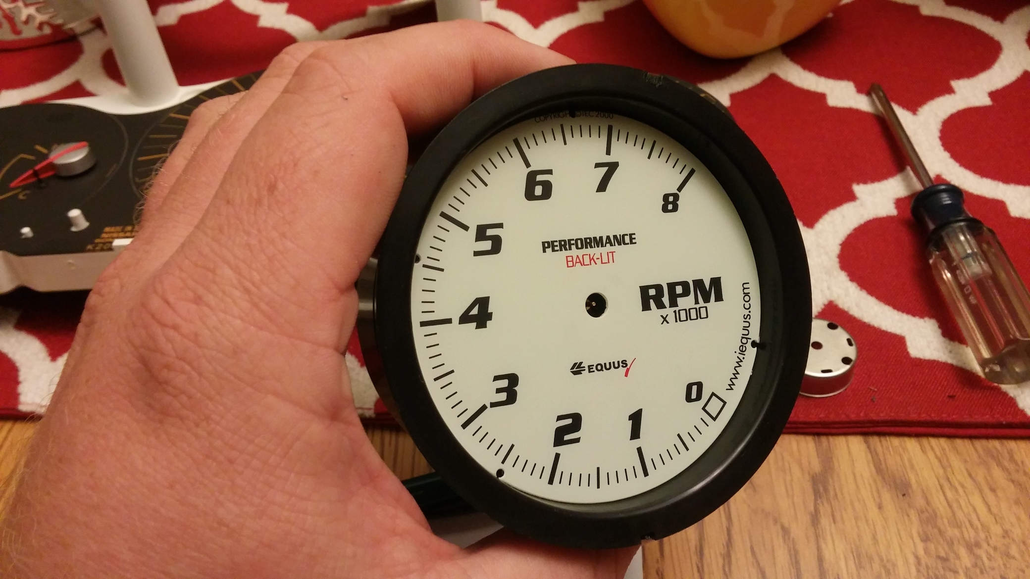
Equus Tachometer p/n: 8068 $79.99 at AutoZone (This is the only tach I know will work for this at this time. I originally had the cheaper $40 chrome bezel version Equus gauage. THAT ONE WILL NOT WORK)
Step 1: Remove stock gauge cluster from car and remove all plastics. If you need some help, check out this YouTube vid How To Remove 350Z Gauge Cluster
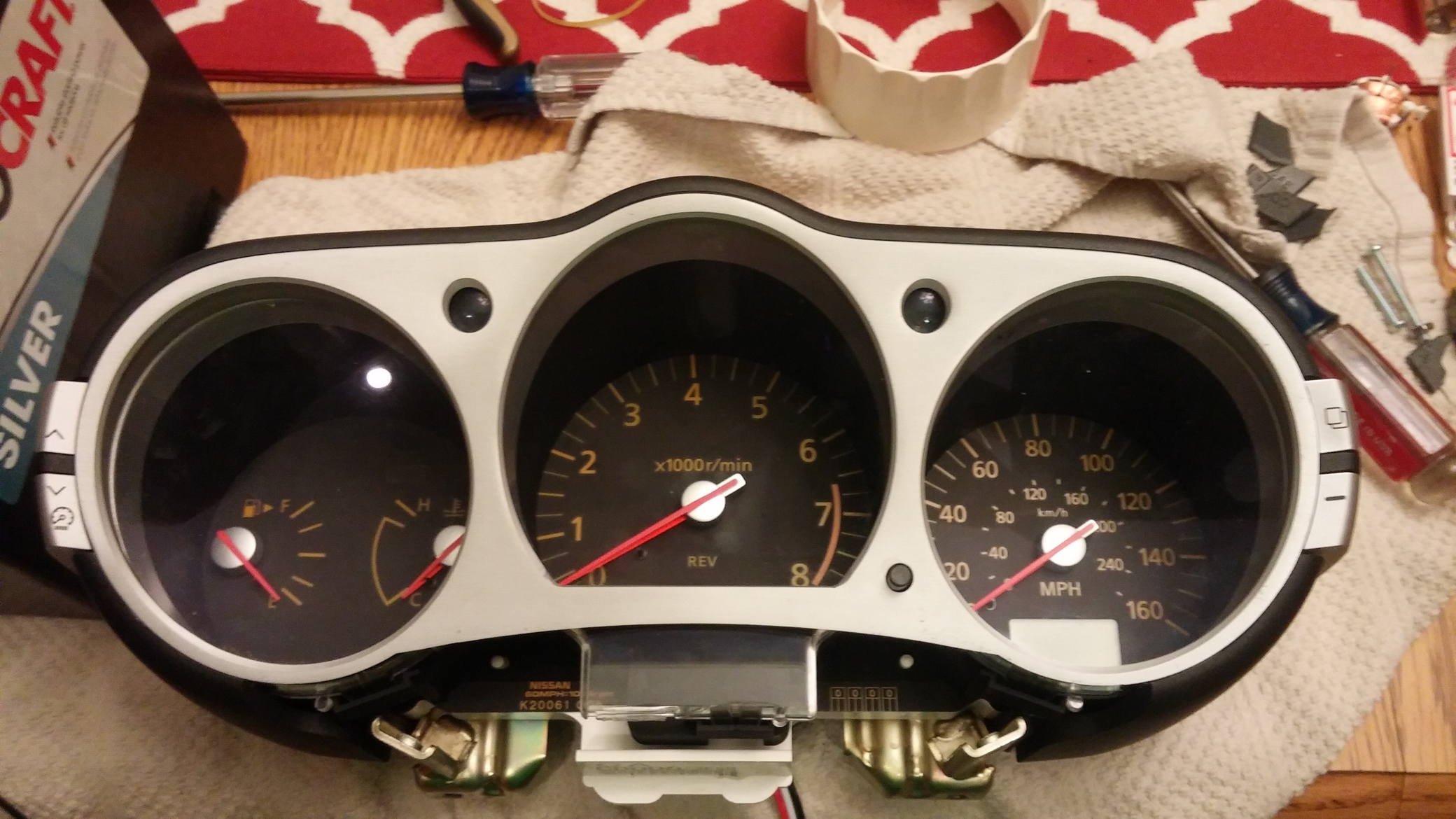
Step 2: Disassemble the gauge cluster. Take your time, nothing takes a lot of yanking to get off. Make sure you have all the little screws removed . You will get it down all the way to just the gauge face and circuit board.
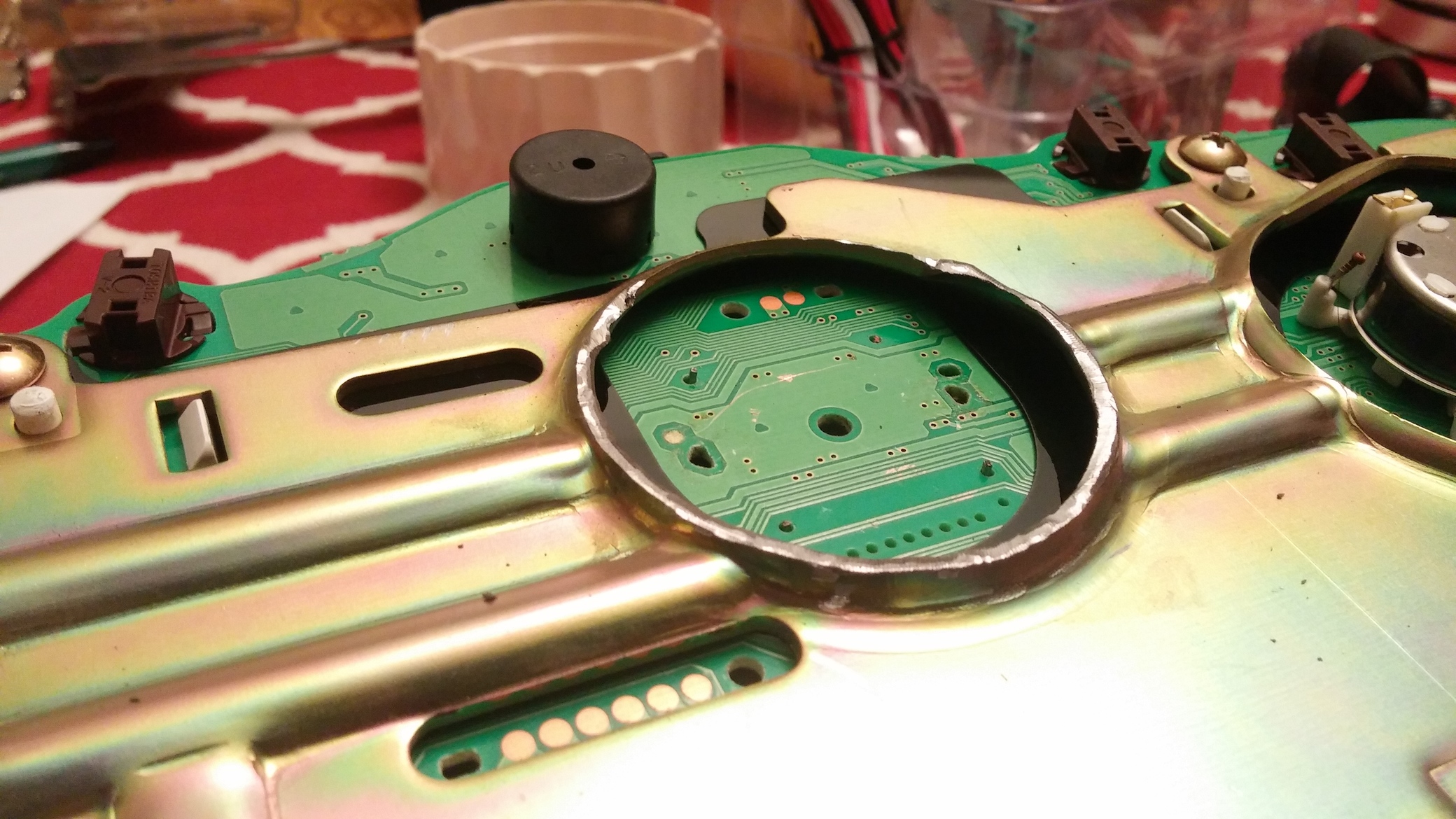
Step 3: Remove the factory 350Z tach needle. Mine was on there pretty tight. Be sure to pull straight up so you don’t break it.
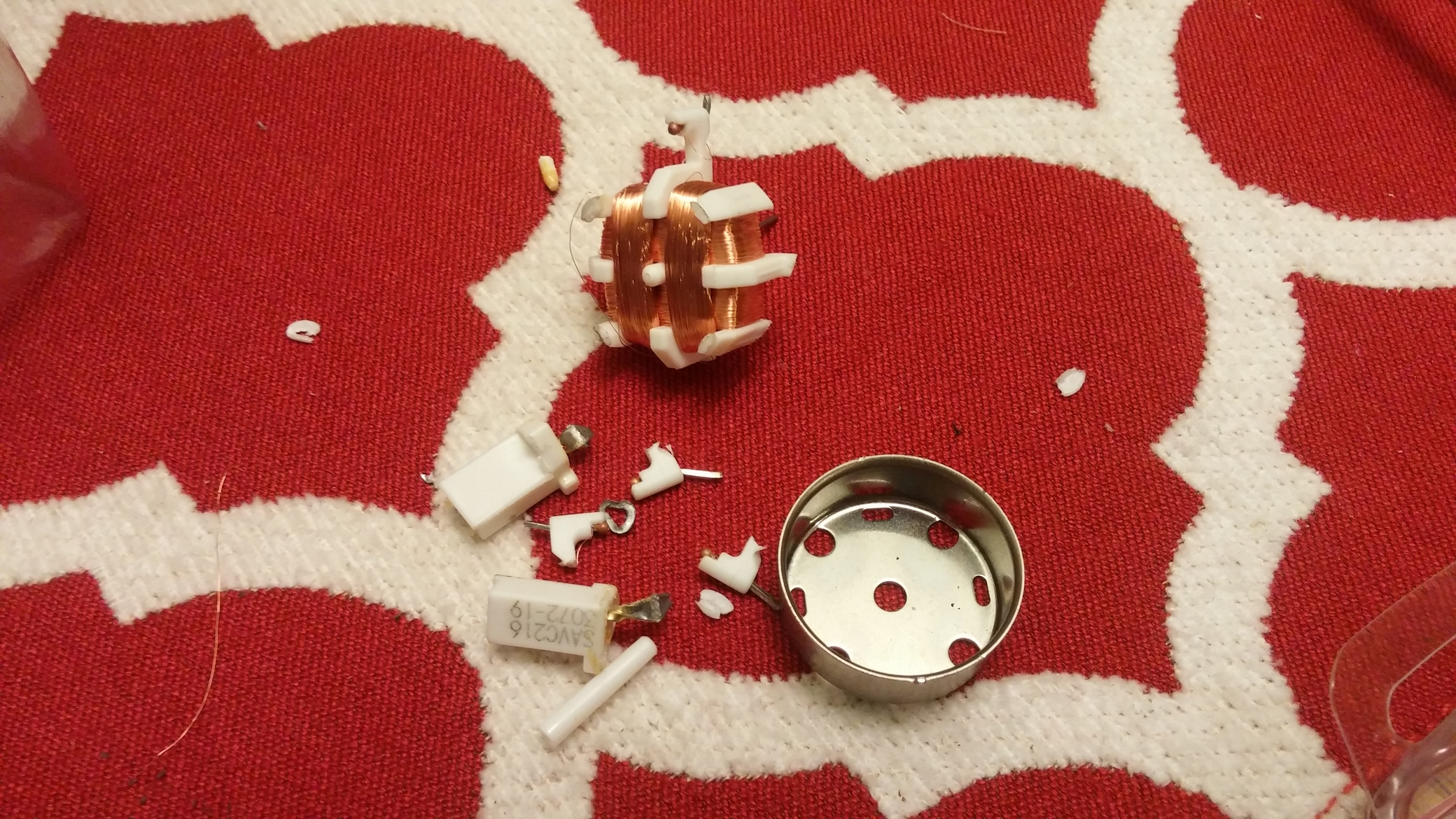
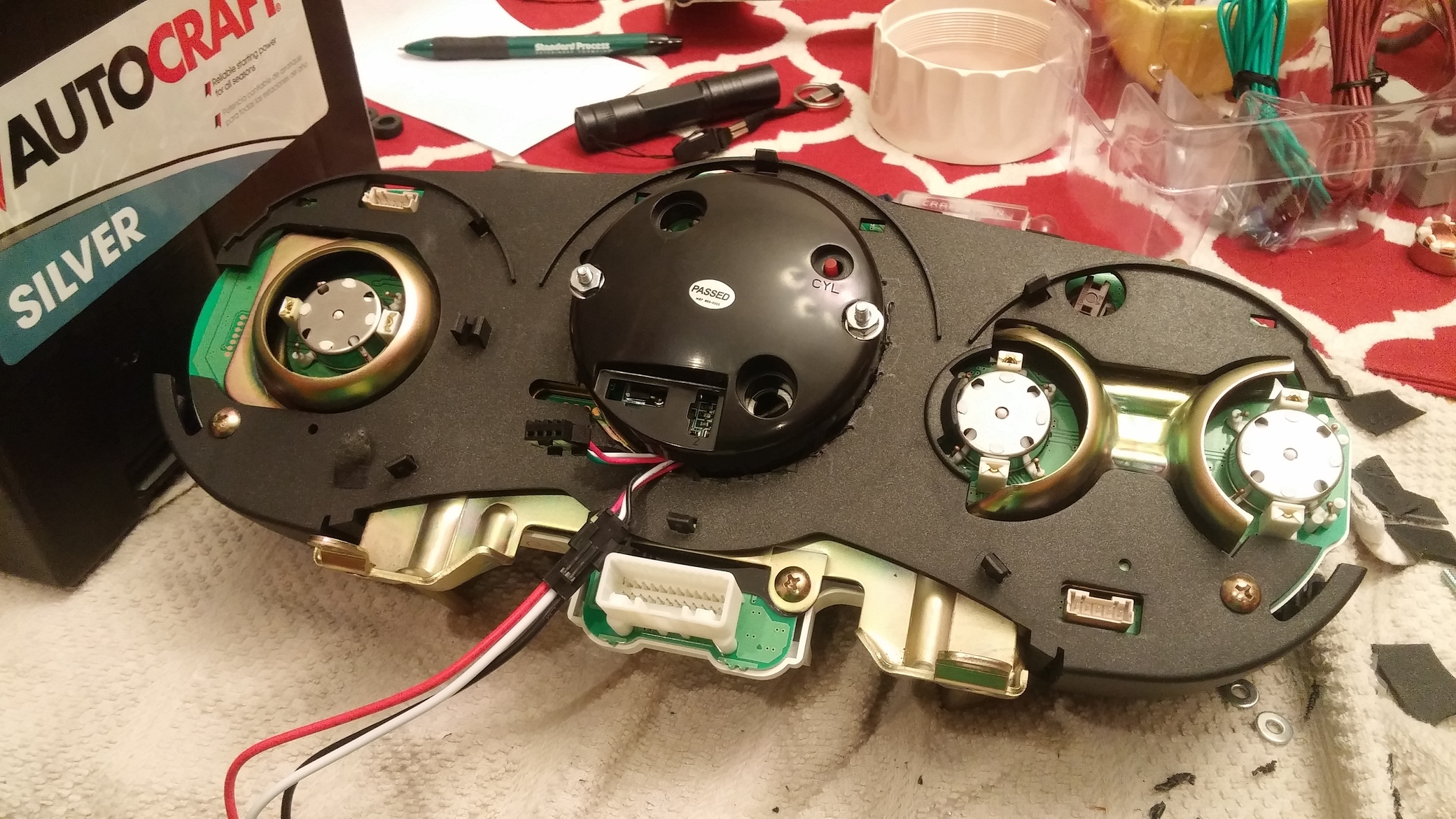
Step 4: Remove factory tach motor. It is attached to the circuit board. I just broke the legs off and wiggled the parts until they broke off. Your stock cluster and circuit board is now ready
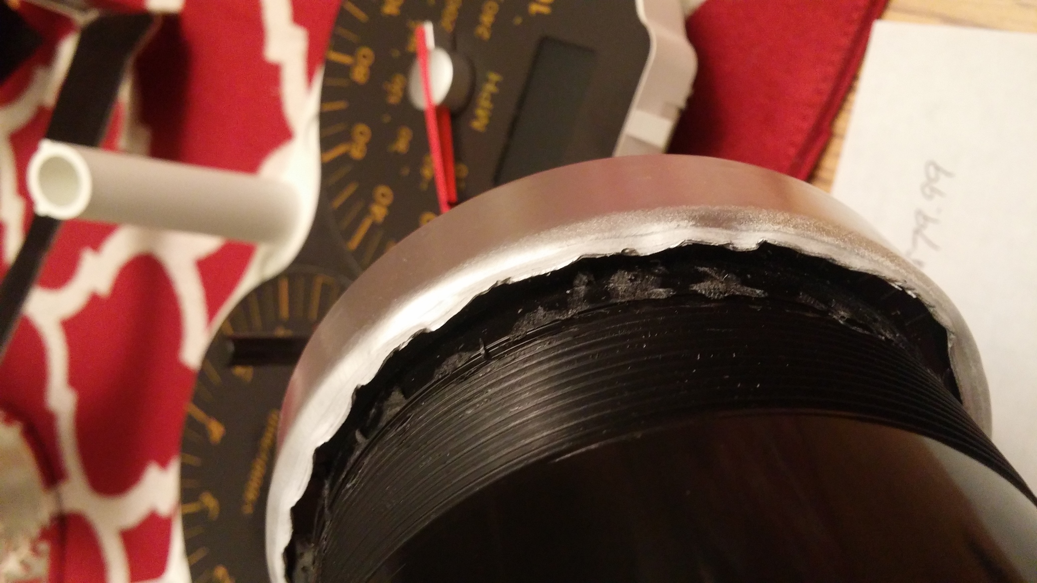
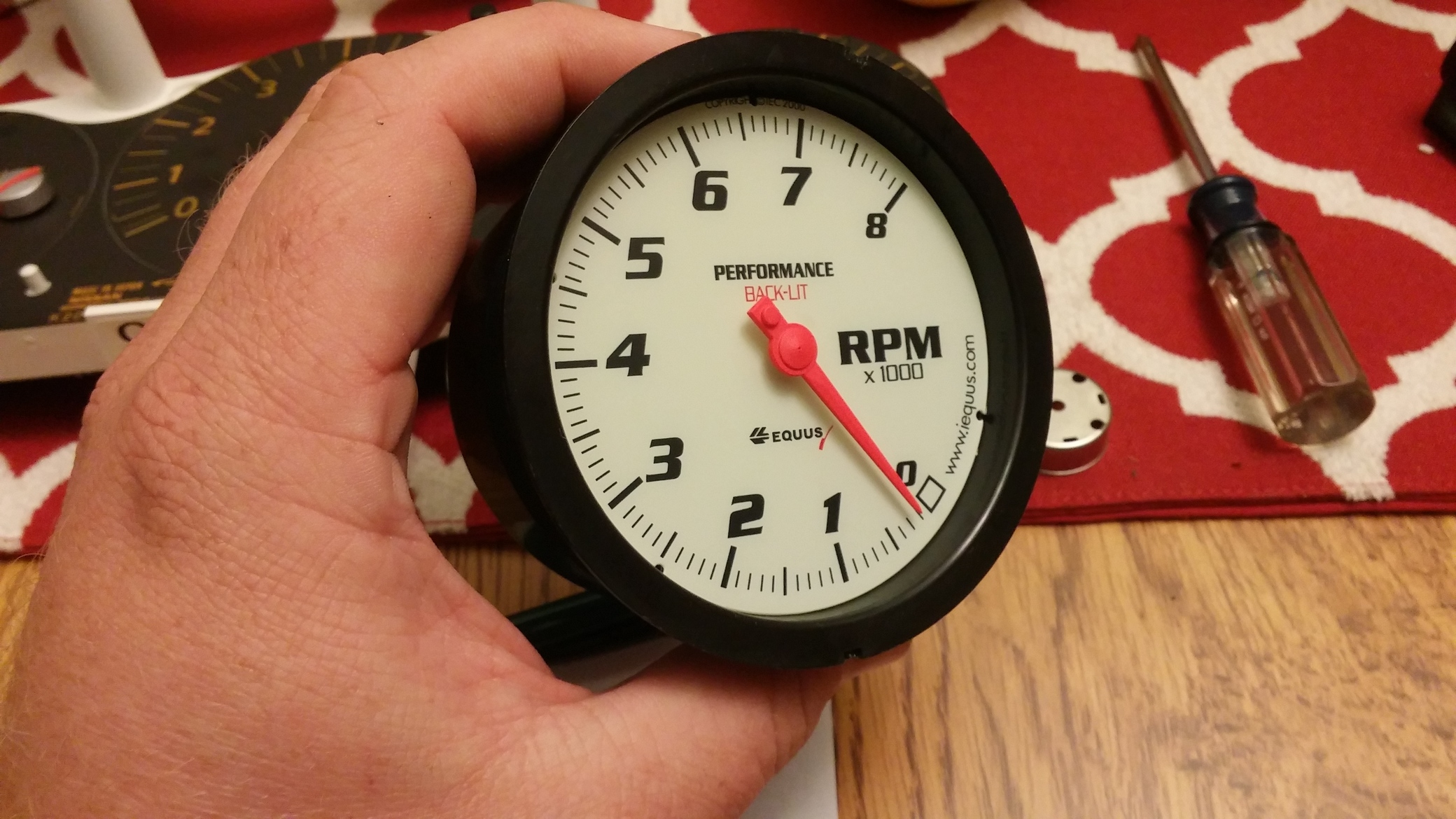
Step 5: Now you’re going to destroy that $80 tach you bought. This is the point of no return on the aftermarket tach. You go past this step, you will not be able to return it. Take a flat head screw driver and pry up the metal bezel from the back side of the tach. Its just thin metal crimped/folded over the plastic housing. Keep prying up all the way around, eventually it will come off.
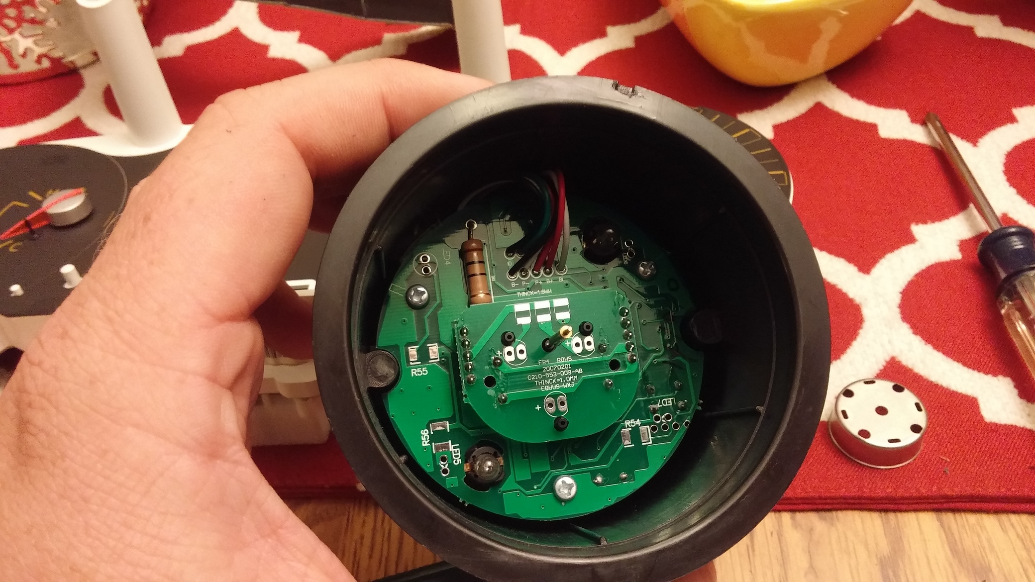
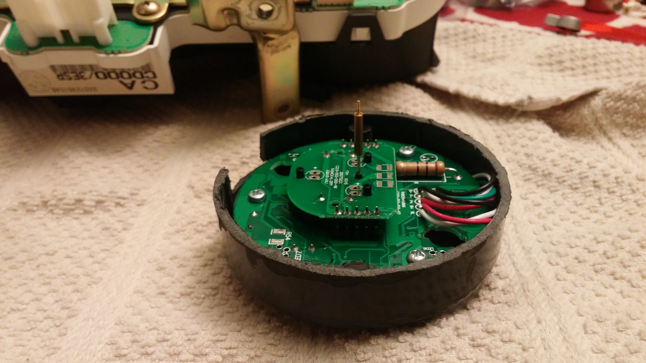
Step 6: With the Equus bezel and window removed, pull the needle (straight up) off the Equus gauge. Then you can remove the Equus white face gauge as well to expose the guts.
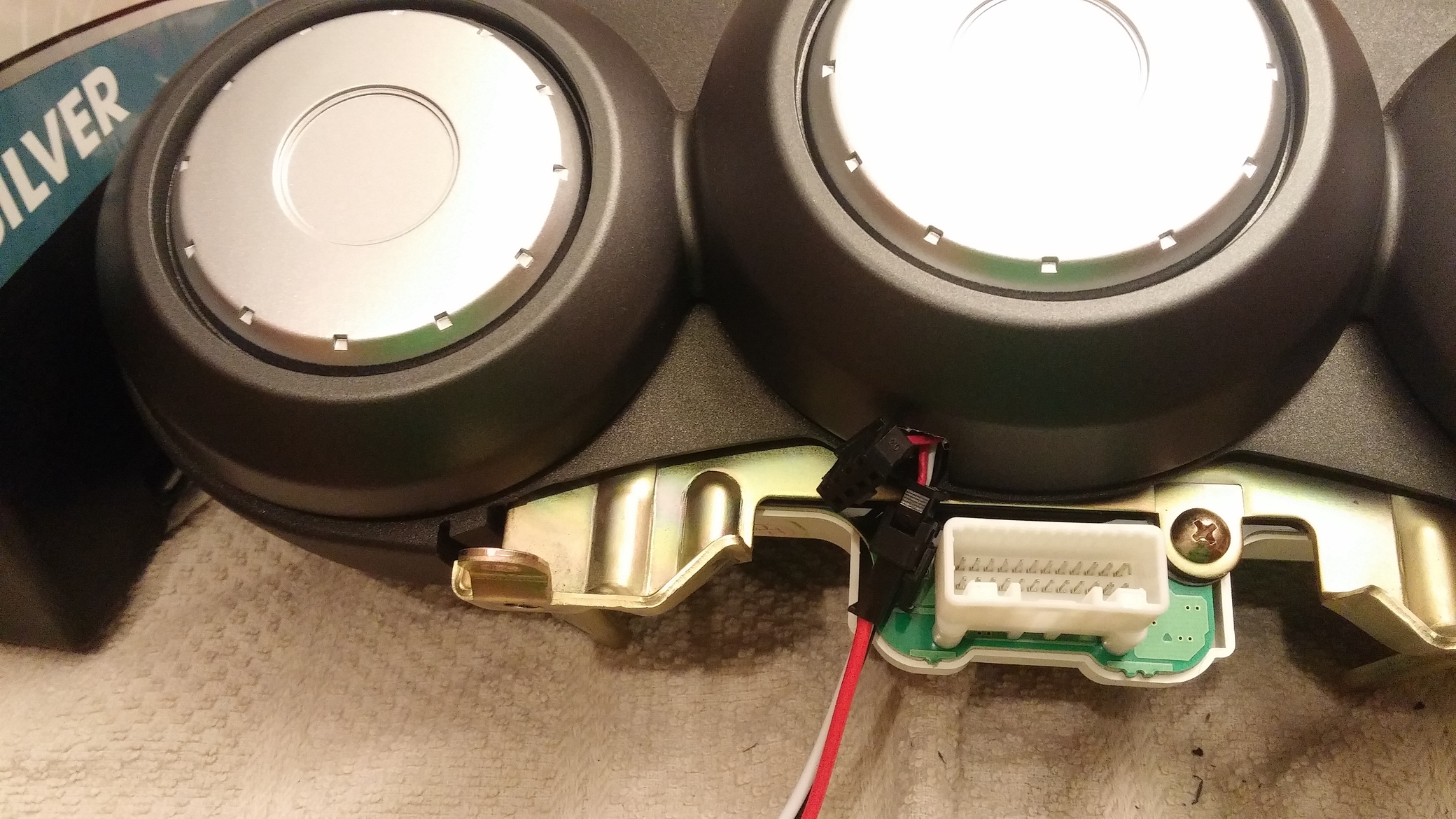
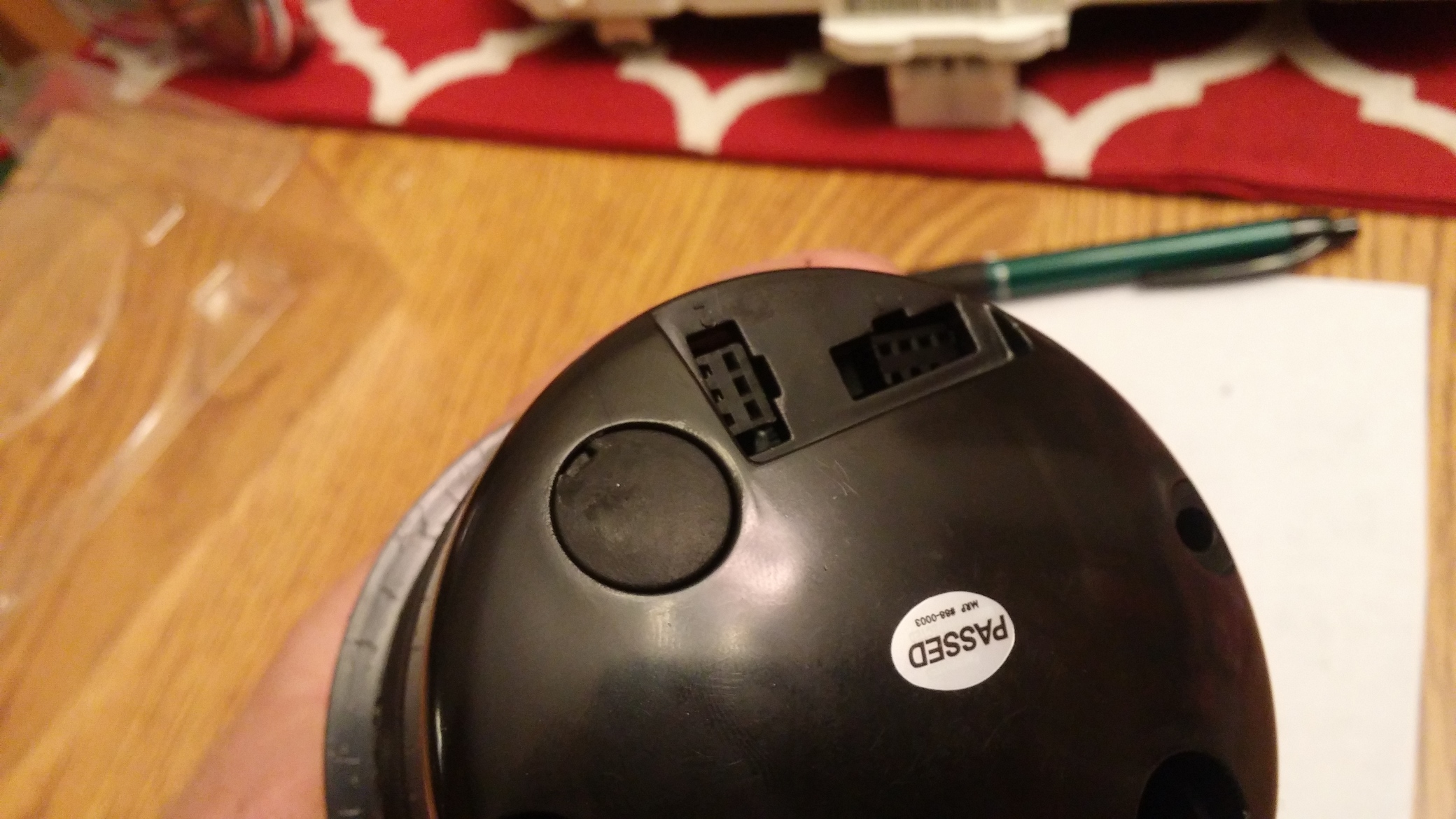
Step 8: There are 3 small screws holding the circuit board in. Remove those.
Step 9: Squeeze the tabs on the wire connectors to remove them from the housing.
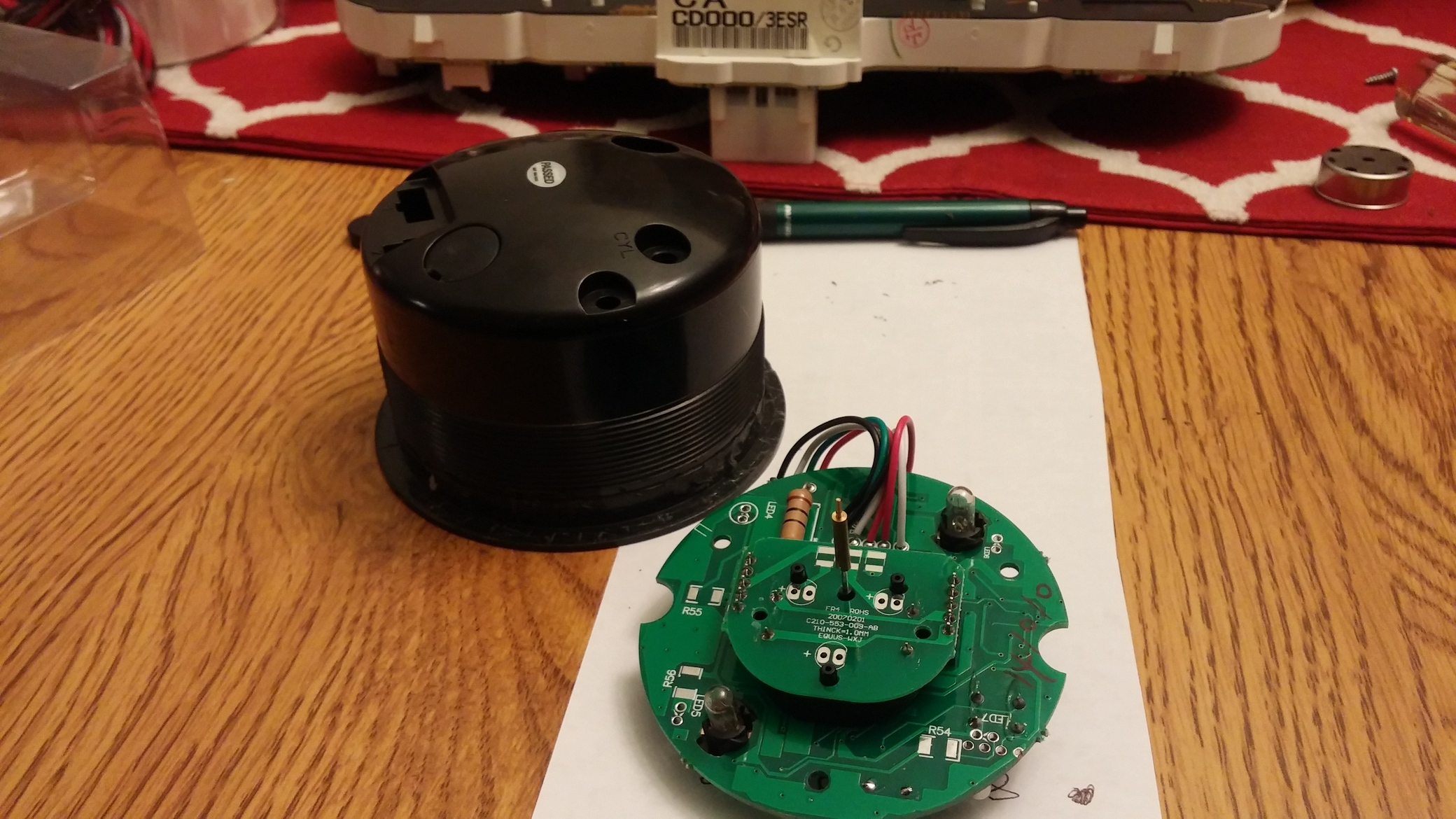
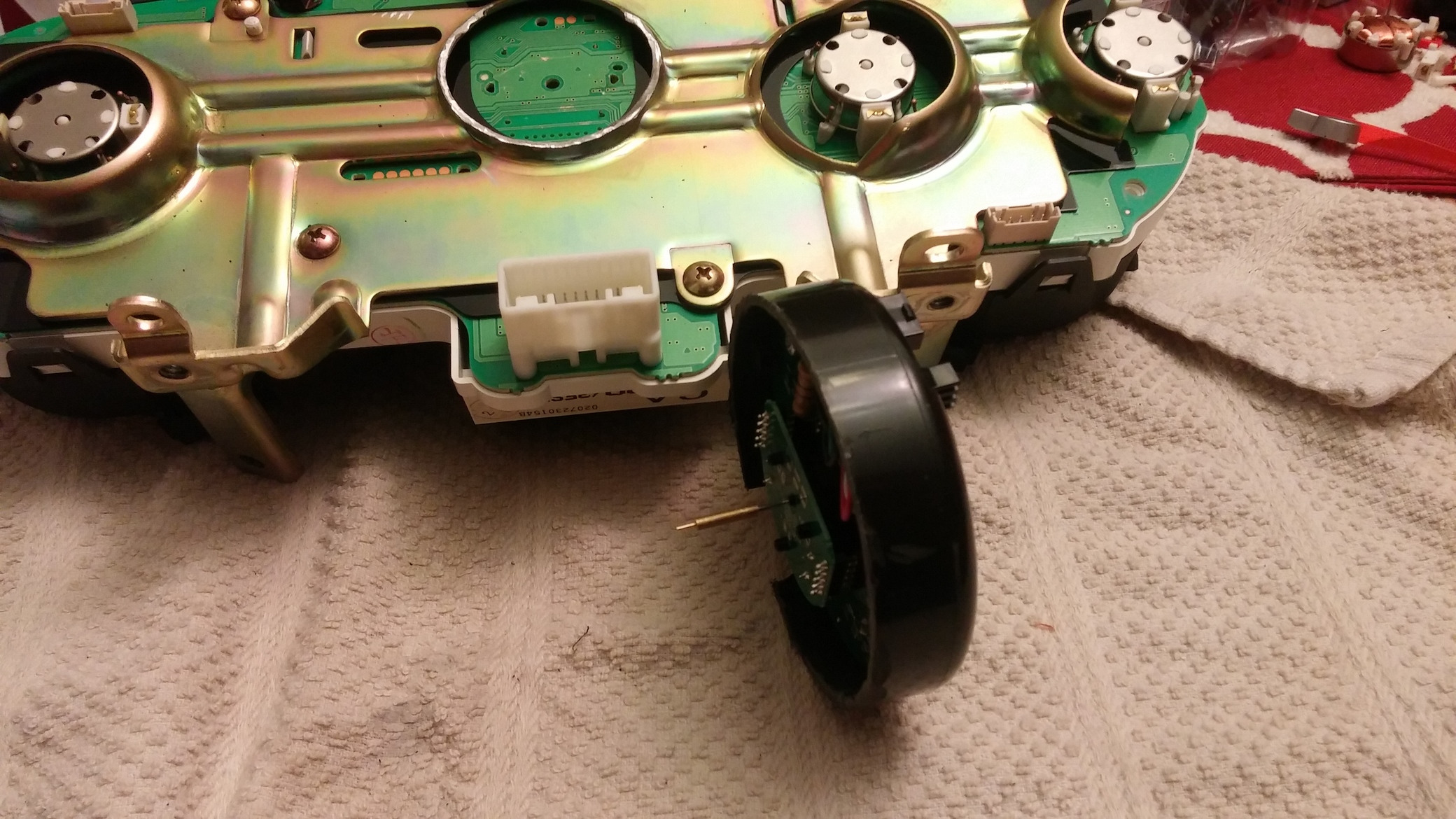
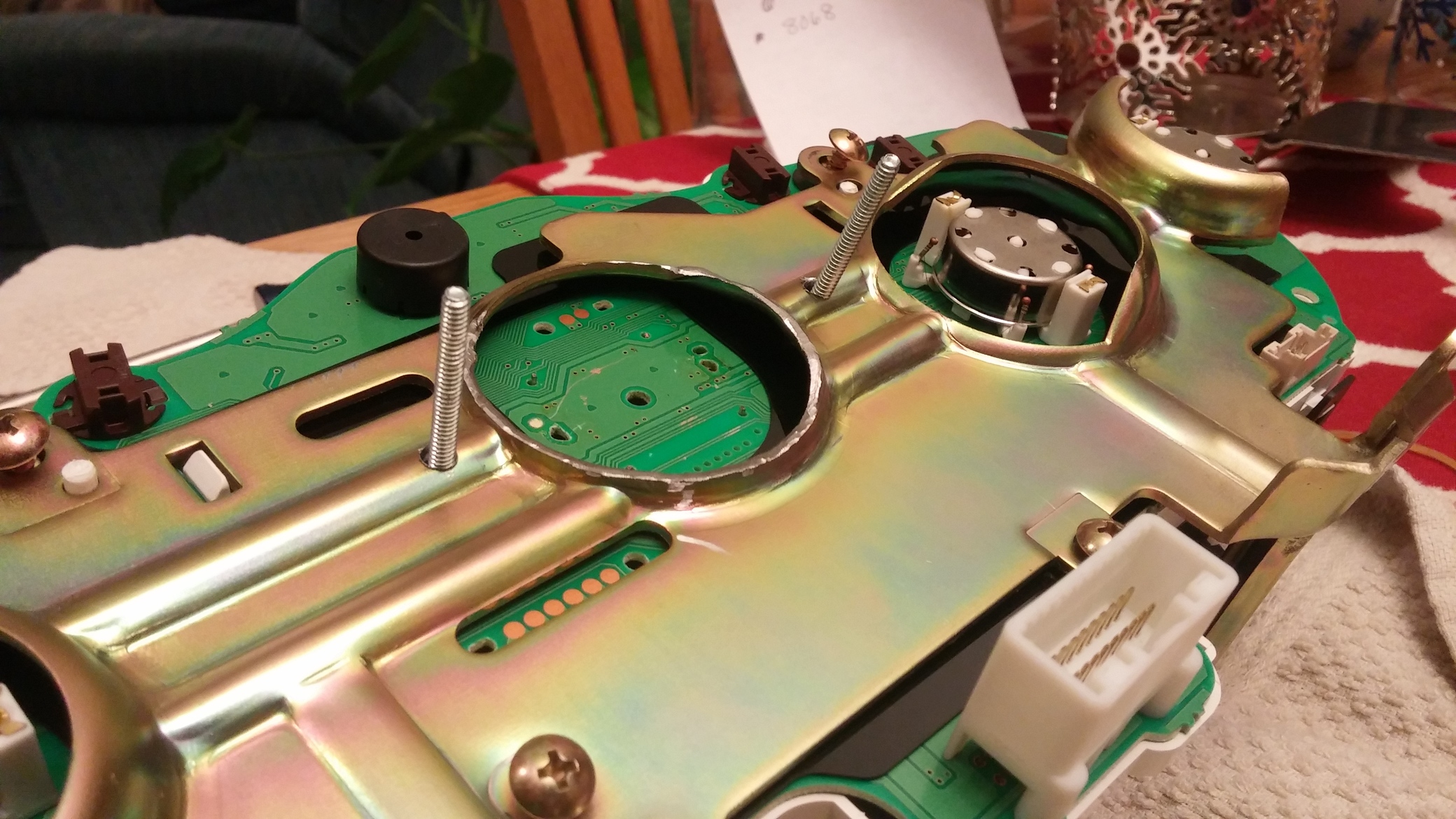
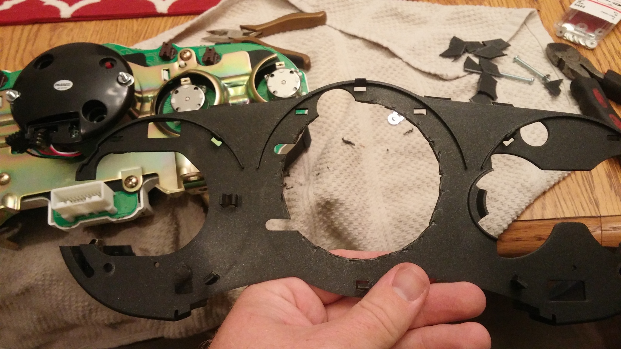
Step 10: Now you are going to modify the metal bracket you removed from the back of the circuit board. You need to do this to make clearance for the smaller raised circuit board on the aftermarket tach motor.
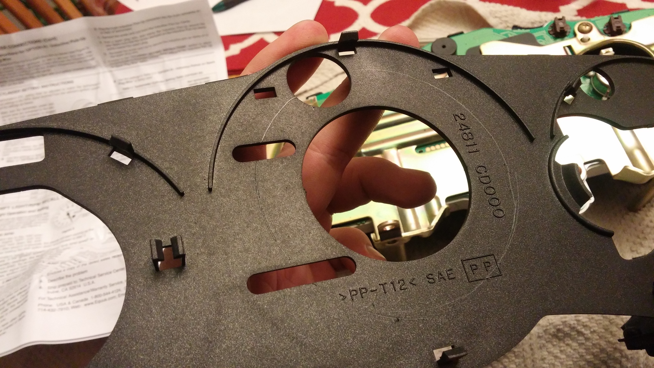
Step 11: Trim the Equus black gauge housing down. You want to trim this down enough that when you reinstall the circuit board into the black housing, then lay its on top of the metal bracket, that the stock needle is at the proper height sticking through the stock gauge face. I trimmed mine down so that the housing is still slightly above the screw bosses at 3 and 9 o’clock on the housing. You will have to trim a clearance hole for some items on the circuit board. You will also want to cut a clearance hole for the wires to come through. You will not be clipping them back into the housing.
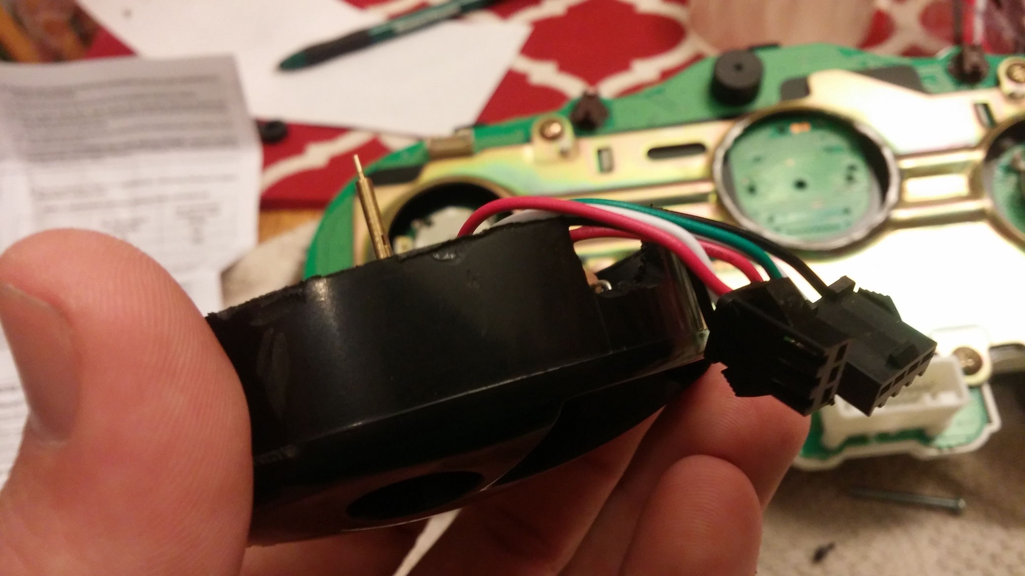
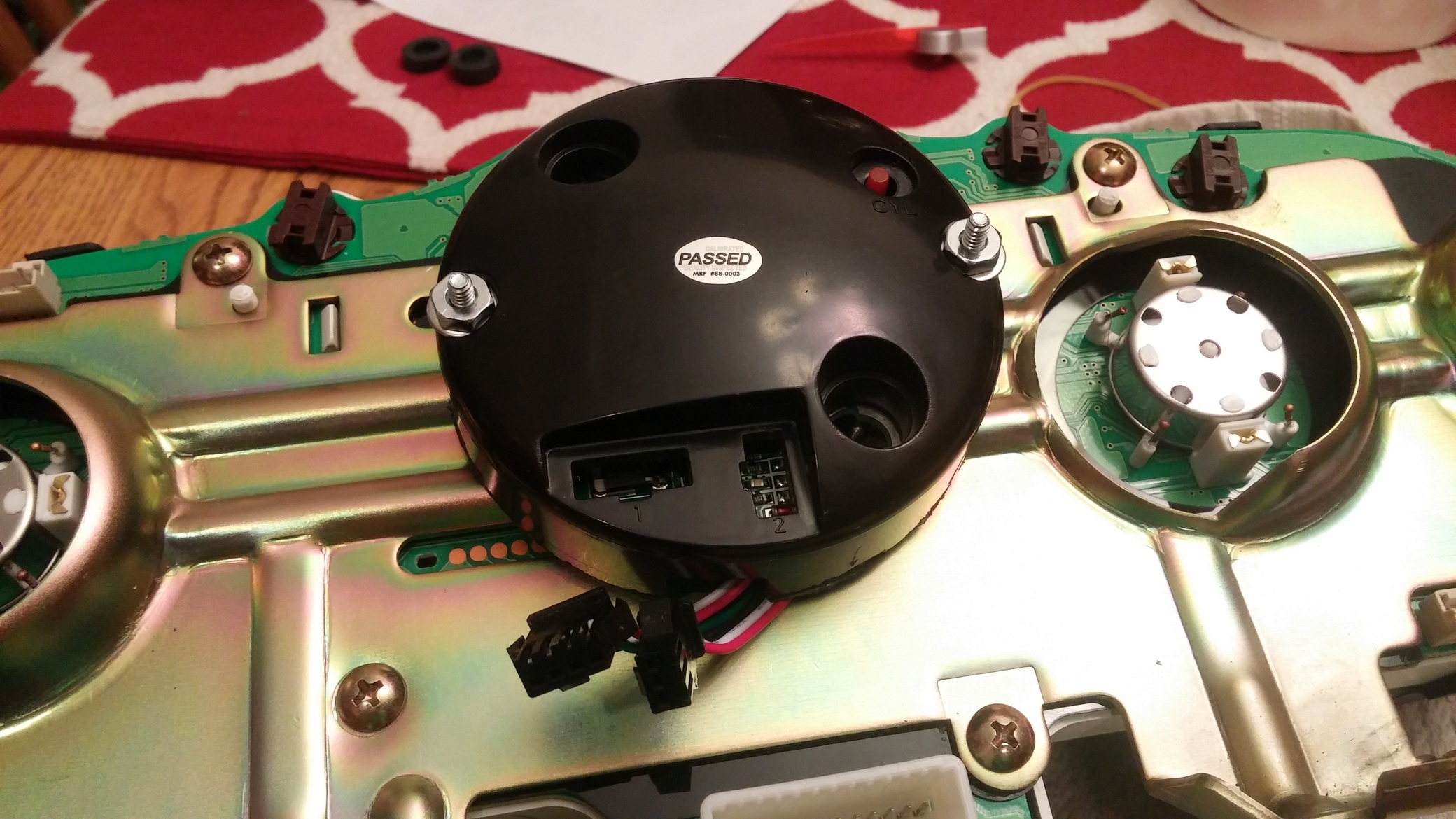
Step 12: To attach the modified Equus tach to the gauge cluster we are going to use those two screw bosses at the 3 and 9 oclock positions. Put your modified Equus housing with the tach drive shaft through the circuit board. Double and triple check this height, and make sure the 350Z needle works with the depth you have set.
Drill holes all the way through those screw bosses large enough for a #6 screw. Use those holes to mark the position on the metal bracket that you need to drill. A #6 x 1.25″ long screw was the perfect length.
Step 13: Attach your modified Equus housing to the metal bracket and tighten down. Take extra care to make sure the tach needle drive shaft is centered in both the circuit board and the gauge face.
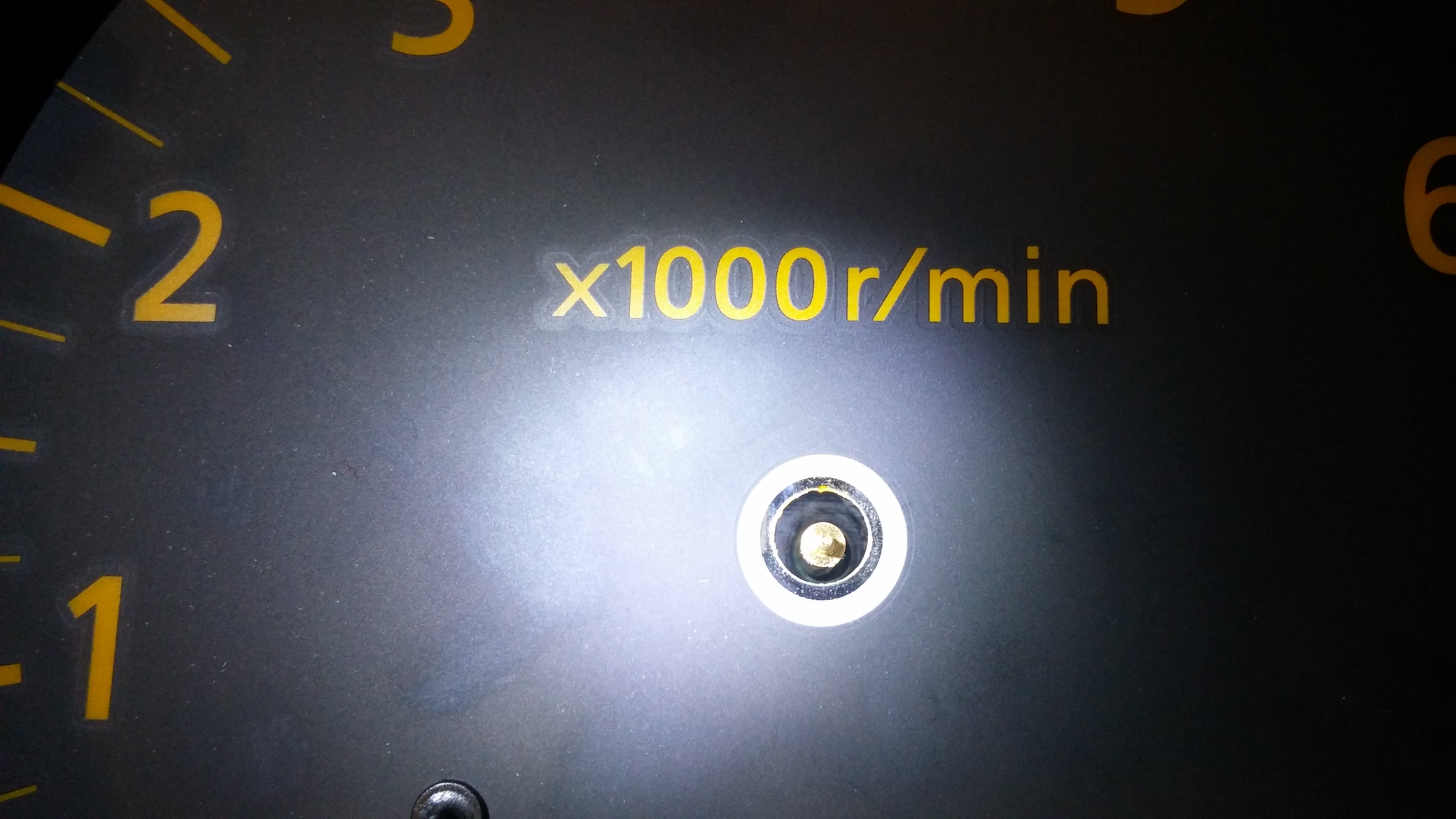
Step 14: At this point you will now set the needle on the gauge face. You will need a 12V battery. This Equus tach has a self zeroing feature that every time it gets power, its does a gauge sweep. connect the red/black/white/ wiring harness. Connect the red and black wires to the battery, and you will see the tach motor doing its zeroing/sweep. When it returns to its “zero” position remove power. At this point you will want to push the factory tach needle on. If you place the needle against the “zero” needle stock on the gauge face this is what happens:
500 rpm: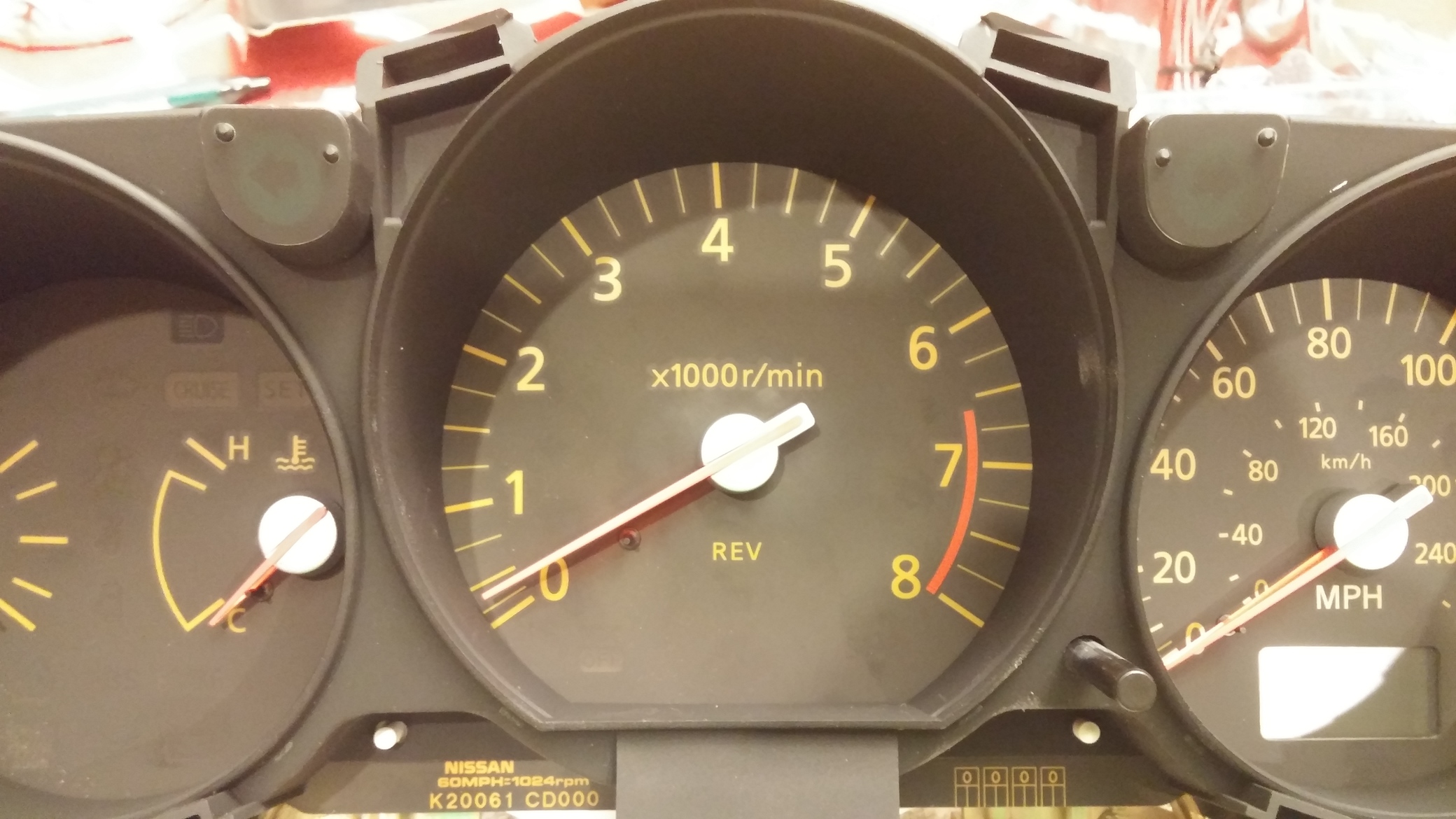
1000 rpm: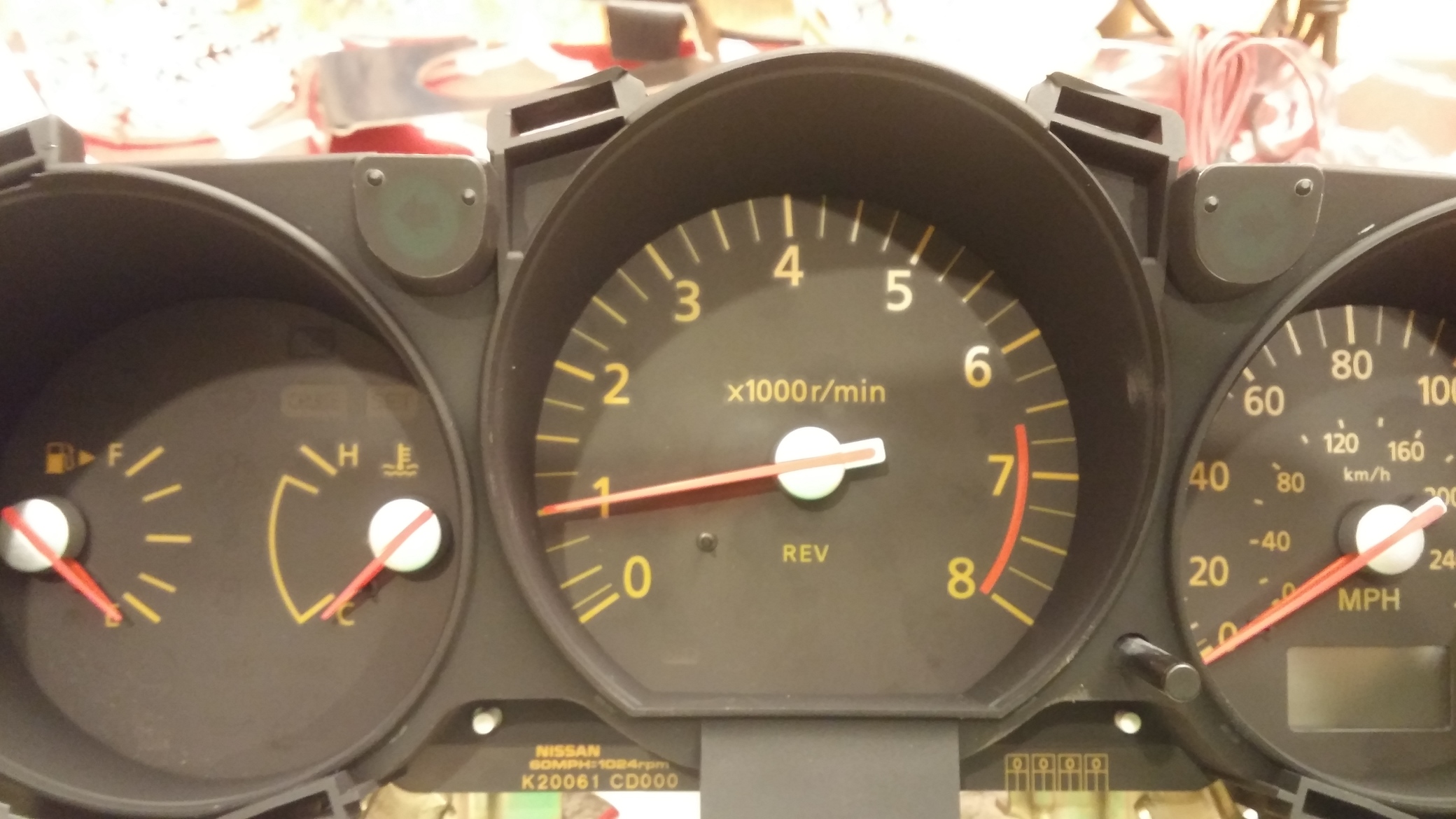
2000 rpm: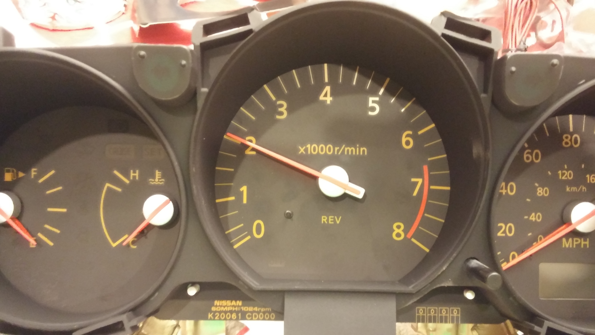
So far so good, right? Lets continue
3000 rpm: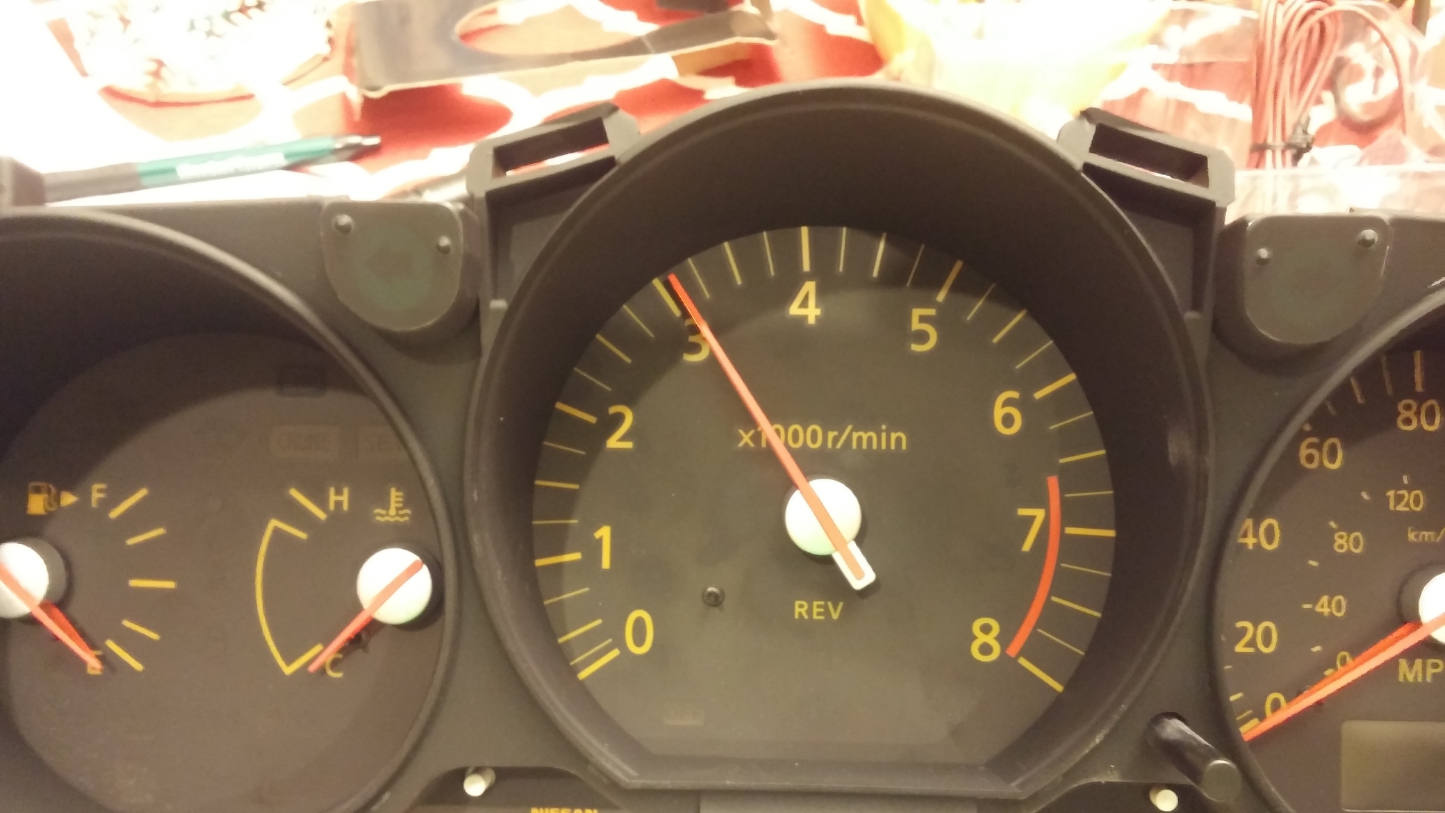
4000 rpm: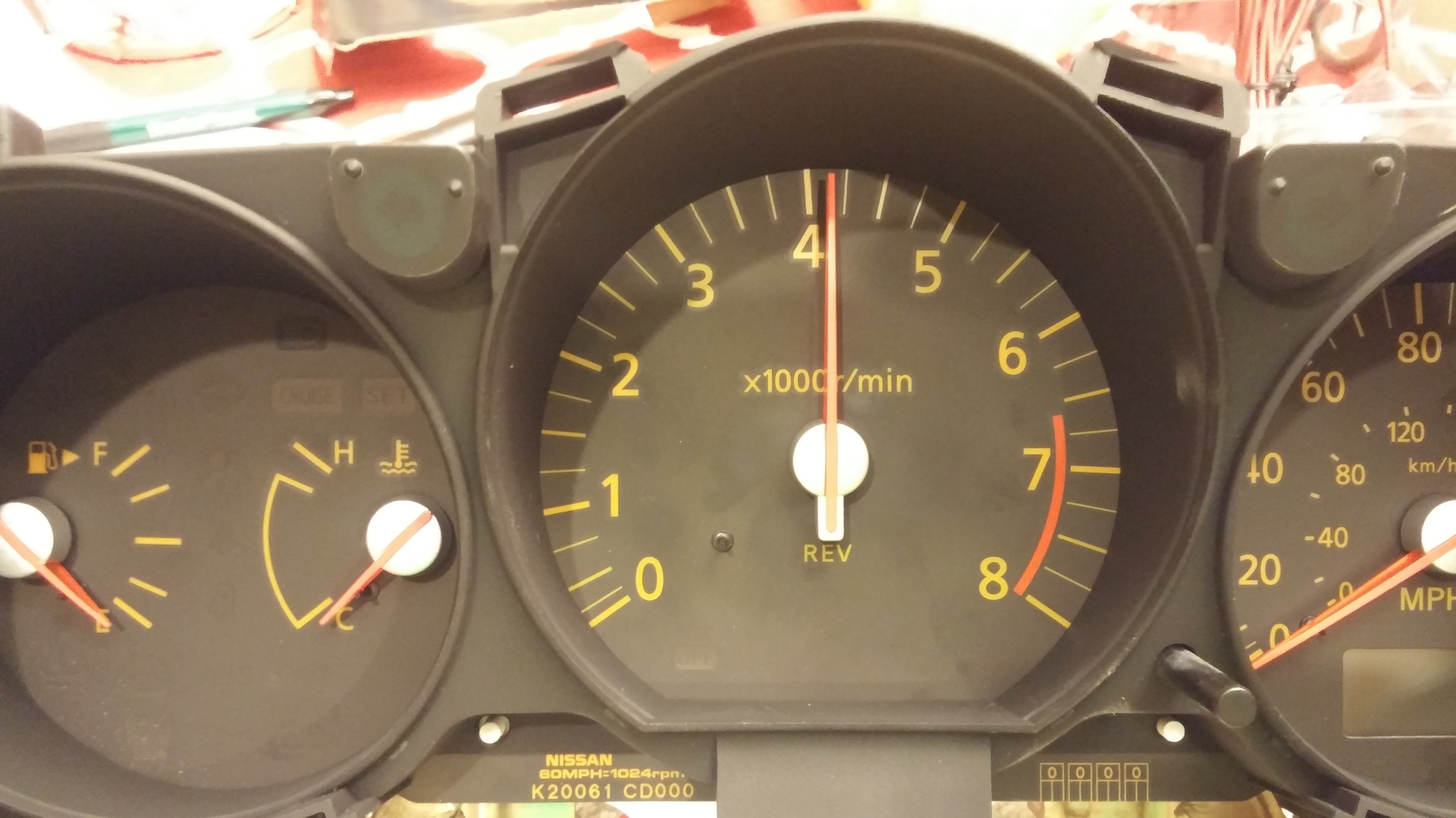
5000 rpm: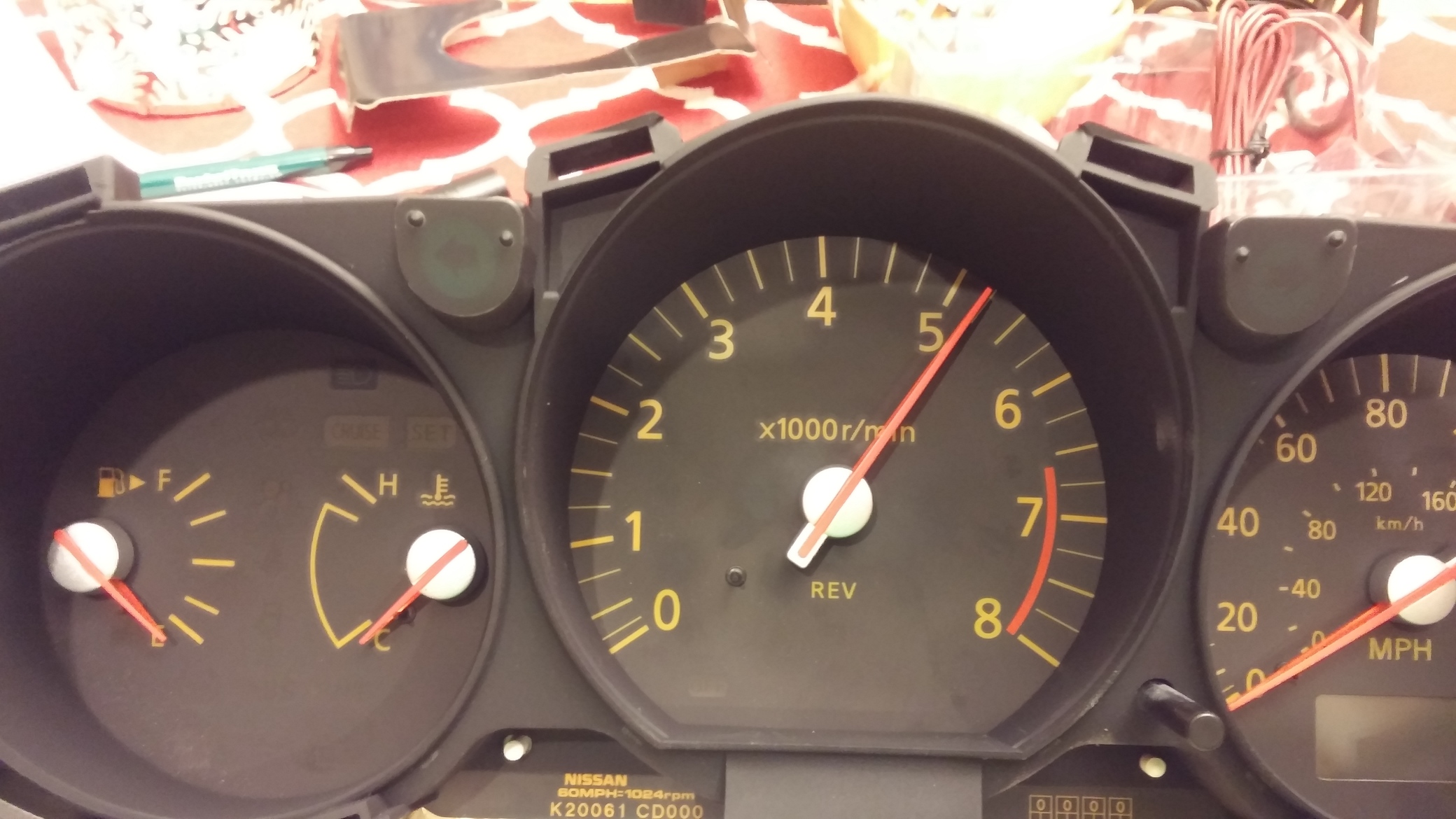
6000 rpm: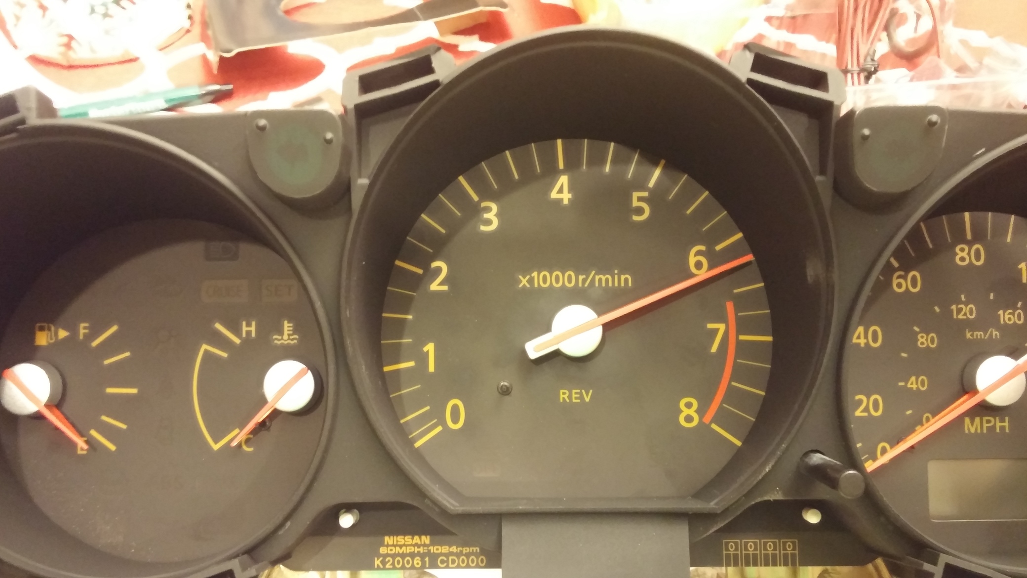
This was done using the “set the no. of cylinders” method with the gauge. As you can see this tach motor doesn’t exactly match. This bothers me. I’m not sure how to fix it. I’ve ruined $80 at this point so I’m going to use this for a little while. Also, the sweep of the Equus tach is a much larger range, so the needle runs into the bottom of the gauge cluster. Someone could try cutting some clearance into the bottom plastic if they wanted. I wasn’t sure I was ready to start cutting my gauge cluster up yet, so I didn’t do it.
Don’t forget to set the Equus tach to the 8 cylinder setting after playing with the needle setting.
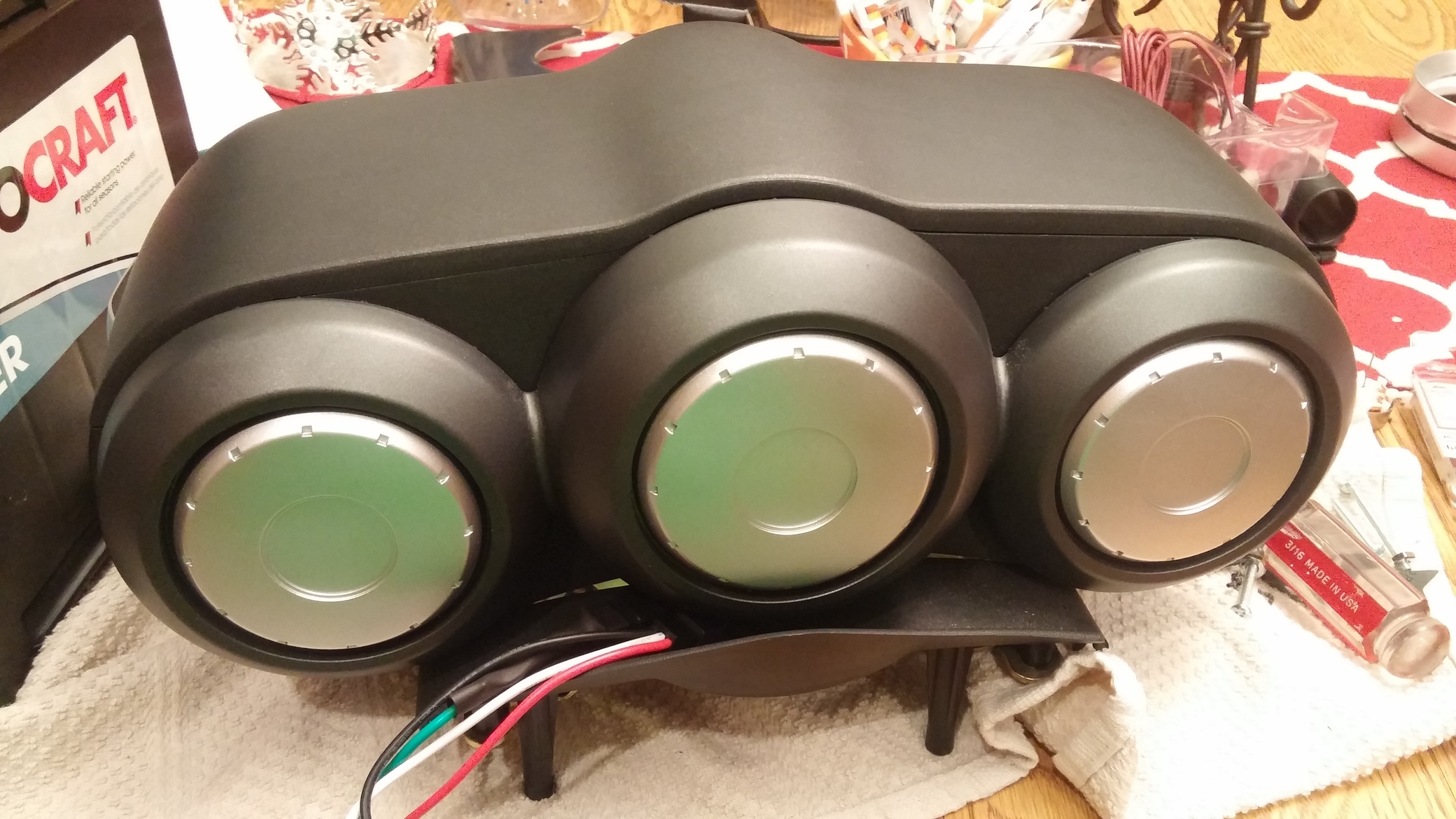
Step 14: you’ll need to clearance the black plastic housing for the back of the stock gauge cluster. Pretty easy.
Step 15: Reassemble. That’s it. Put it all back together and wire it into the car. You’ll have to cut a small hole for the wires from the tach to come out the back of the pods. This position worked, but i’d move it up to more the 8 oclock position if I were to do it again, as its a little tight to the plastic column cover.